Based on the successful blog posts about internet radio (Part 1, Part 2) I am introducing a clock radio today. The special thing is that an AZ-Touch with a 2.4 inch or 2.8 inch touchscreen is used. Operation takes place exclusively via the touchscreen. There are two alarm times, which can be assigned to any day of the week. Of course there is also a sleep timer. The brightness can be adjusted so that the display does not disturb you at night. With an optional LDR, the display brightness can be automatically adjusted to the room brightness. Volume, sleep time, display brightness and station selection can be adjusted via the touchscreen. Wake-up times and the stream URLs of the radio stations are configured via a web interface.
Required hardware
| Number | Component | annotation |
|---|---|---|
|
1 |
AZ touch with 2.4 inch display or 2.8 inch display |
|
|
1 |
|
|
|
2 |
|
|
|
1 |
|
|
|
1 |
|
|
|
1 |
|
|
|
1 |
Optional |
circuit
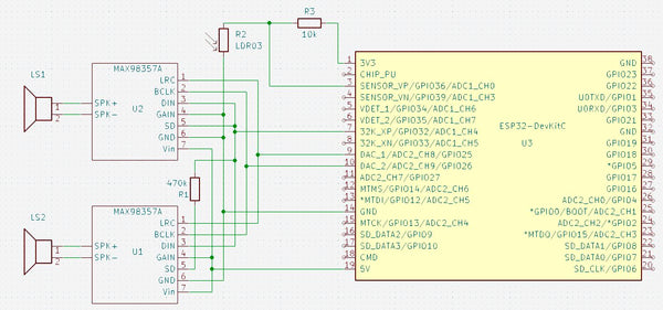
The circuit diagram only shows those parts that are not present in the AZ-Touch. The following images show how to expand the AZ-Touch circuit board accordingly. For the audio amplifiers, two 7-pin female connectors are attached to the perforated grid of the AZ-Touch to plug the audio amplifiers into. Also a 470 kΩ resistor. If you want to use the optional light sensor, you should solder a two-pin pin strip at 3.3 V and GND, as well as a single-pin pin at A0.
The second illustration shows how the wiring should be done on the back. The contours of the female connectors and the resistor are shown in yellow.

assembly
To accommodate the speakers, the AZ-Touch has a back wall that transforms it into a desk housing. The back panel can be made with a 3D printer. It also has an opening for the DC socket. File for printing the back panel.


There is one for installing the optional LDR mounting plate, onto which the LDR module can be screwed. A 5mm hole is drilled at the top of the housing and then the mounting plate is glued to the back wall with double-sided adhesive tape so that the LDR lies in the hole.
software
The sketch has been broken down into several parts for clarity. A function provided by the Arduino IDE is used for this purpose. If there are other “.ino” or “.h” files in the same folder in addition to the main sketch, which has the same name as the folder, the compiler will append them to the main sketch in alphabetical order.
Since the entire code has become very extensive, it is only available for download.
The ZIP file contains the folder with all associated files. It must be unpacked into the project files folder (often Documents\Arduino\). The individual parts are briefly described below. A detailed description can be found as comments in the code.
- radiowecker.ino: This is the main sketch. Global variables and data structures are defined.
- findNextAlarm() looks for the time and day of the week on which the alarm clock should be activated. The result is in the global variables alarmday for the day of the week and alarmtime saved for time in minutes. If no next appointment has been found, alarmday set to 8.
- set up() After initializing the serial port, the configuration data is read from the preferences. The setup functions of the individual program parts, with the exception of the web server and OTA, are then called. This is followed by establishing a connection to the local WLAN. If the connection was not successful, information about the configuration is shown on the display. If the connection is successful, the real-time clock is initialized. Now the setup for web server and OTA can also be called up.
- loop() first checks whether there are OTA requests and then whether there are requests for the web server. It checks whether the connection to the WLAN still exists. If the connection is established, the audio stream and the two encoders are checked for events. The time display is updated once a minute and a check is made to see whether the alarm clock needs to be activated. If the alarm time and day of the week match, the radio stream is started and played at the set volume. If the connection was interrupted for more than 5 minutes, the ESP32 will be restarted.
- 01_ziffern.ino: Defines 11 bitmaps with 50 x 70 pixels. These are the numbers 0 to 9 and the colon to represent the time.
- audio.ino: In this part, all functions related to the audio streams are implemented.
- setup_audio() prepares the system. Buffer and stream output are initialized.
- audio_loop() checks the status of the audio stream.
- MDCallback(void *cbData, const char *type, bool isUnicode, const char *string)
is called whenever new metadata is available in the received stream. Title type metadata appears on the display. - stopPlaying() stops playing the stream and releases the associated resources.
- bool startUrl(String url) Starts playing a stream from a given URL. If the start is not successful, false is returned.
- setGain() sets the volume to the value of the global variable
- fonts.h: Two fonts for the text display are defined here. One has a height of 9 pixels, the other 12 pixels. In addition to the 7-bit ASCII characters (codes 32 to 126), there are also the German umlauts Ä, Ö, Ü, ä, ö, ü, ß and the degree symbol (codes 127 to 134). There is a module for conversion tft_display.ino the function encodeUnicode(const char* src, char* dst), which converts text in UTF8 format so that it is displayed correctly on the display. For easier handling, two macros are defined: FNT9 for the 9-pixel font and FNT12 for the 12-pixel font.
- index.h: Contains the HTML pages for the web server. With the command sequence
const char MAIN_page[] PROGMEM = R"=====(
any text………
)=====";
Any text can be built directly into the program memory as a constant. This is very useful for HTML pages as they can then be designed and tested outside of the IDE. These pages use jQuery, Ajax and JavaScript. The advantage of Ajax for interactive pages is that when changes occur, only the changed part of the page is updated. Three HTML constants are defined.- OPTION_entry a template for entries in the selection list for the radio stations
- MAIN_page the main page with configuration and maintenance of the channel list
- CONFIG_page Page for entering the access data if the ESP32 is in access point mode for the initial configuration.
- knoepfe.h: HHere a bitmap with 320 x 64 pixels is defined that represents the heads on the configuration page. Each of the five buttons has a size of 64 x 64 pixels.
- ota.ino: The functions for updating the firmware via WLAN can be found here.
- setup_ota() the hostname and password are set. Callback functions are then registered.
- ota_onStart() is called when starting an OTA upload. The display is cleared and a corresponding message is shown in the first line
- ota_onEnd() is called after the upload has finished. A corresponding message is displayed.
- ota_onProgress(unsigned int progress, unsigned int total) is called up at regular intervals during the upload and provides information about the progress. The display shows the progress in percent and as a bar.
- ota_onError(ota_error_t error) is called when an error occurs. The error message is shown on the display.
- stations.ino: defines a program memory constant with the default channel list.
- setup_senderlist() fills the channel list in RAM with the channel list from the preferences. If there is no channel list there, the default channel list is used.
- restore(): Fills the channel list from the default channel list and saves it in the preferences. The function is helpful if the channel list is mixed up.
- saveList(): Save the station list from the RAM in the preferences.
- reorder(uint8_t oldpos, uint8_t newpos): Moves the sender entry at the position oldpos to the position newpos. Entries in between are moved accordingly.
- tft_display.ino: contains all functions for controlling the display and touchscreen.
- onTouchClick(TS_Point p): Callback function that is always called when you briefly tap the touchscreen. The parameter p indicates the point on the display that was tapped. The coordinates are x and p.y. The zero point is in the top left corner.
- setGainValue(uint16_t value): The volume slider is updated to the value passed.
- setBrightness(uint16_t value): The brightness slider is updated to the value passed.
- setSnoozeTime(uint16_t value): The sleep time slider is updated to the value passed.
- setBGLight(uint8_t prct): The brightness of the backlighting of the display is set to the transferred value in percent. If the value is 0, the brightness is set depending on the light sensor.
- selectStation(uint16_t x): Depending on the x position, the next or previous entry in the channel list is displayed on the configuration page. Entries that are not activated are skipped. If x < 50, the previous entry is displayed. If x > 270, the next entry is displayed. Nothing happens for all other values of x.
- toggleRadio(boolean off) : Depending on the value of the parameter off Playback of the MP3 stream is started or stopped. The display then switches to the clock display.
- toggleAlarm(): The alarm clock function is switched. From off to on and vice versa. The display then switches to the clock display.
- startSnooze(): The sleep time is started with the configured value. The display then switches to the clock display. If necessary, the radio will be turned on.
- changeStation(): With selectStation selected station is set as active station. The display then switches to the clock display.
- touch_loop(): Must be called from the main loop and is used to query the status of the touchscreen in order to detect touches.
- setup_display(): The display and touchscreen are initialized.
- textInBox(uint16_t x, uint16_t y, uint16_t w, uint16_t h, const char* text, uint8_t align = ALIGNLEFT, boolean big = false, uint16_t fc = ILI9341_WHITE , uint16_t bg = ILI9341_BLACK, uint8_t lines = 1 ): The passed text will be in a rectangle with the width w and the height H at the position x, y (top left corner). If the text is too long, it will be cut off at the last space between words. The alignment can be left, right or centered. Default is left. With the parameter big The font size can be selected with 12 pixels. Default is 9 pixels. Font color and background color can be chosen. Default is white on black. A multi-line display is possible. In this case, the line break always occurs at a space between words. Default is one line.
- updateTime(boolean redraw): The date and time display is updated. Is redraw true, the entire content will be reprinted, otherwise only the changes will be updated.
- displayDateTime(): Calls updateTime(false)
- showProgress(uint32_t prc): Displays a progress bar and the value in percent. Is called in connection with the software update.
- encodeUnicode(const char* src, char* dst): Walks in the text src the UTF8 characters ÄÖÜäöüß° so that they are shown correctly on the display. The result will be in dst The target string must exist in a sufficient size.
- showSlider(uint16_t y,float value, uint16_t vmax): A slider will be at the vertical position y The slider will change according to the value passed value positioned. The parameter vmax indicates the maximum value.
- showGain(): The volume setting bar in the configuration display is displayed.
- showBrightness(): The brightness setting bar in the configuration display is displayed.
- showSnoozeTime(): The bar for setting the sleep time in the configuration display is displayed.
- updateStation(): The name of the channel in the channel selection bar is updated.
- showStationList(): The channel selection bar in the configuration display is displayed.
- showCommand(): The configuration display is displayed at full brightness.
- showStation(): The name of the active station is displayed in the radio block.
- showTitle(): The metadata for the currently playing stream is displayed in the radio block.
- showRadio(): The radio block is displayed.
- showNextAlarm(): The date and time for the next alarm event are displayed on the bottom line.
- showDebugInfo(int16_t v1, int16_t v2, int16_t v3): This function is not used. However, it can be used to show the value of three integer numbers on the display in the bottom line.
- showClock(): The time is displayed. The display will be completely deleted beforehand. If the radio is switched on, the radio block is displayed. If the alarm clock function is active, the next alarm time is displayed.
- webserver.ino: Includes the setup and functions to respond to http requests.
- setup_webserver(): The individual functions for handling http requests are registered and the server is started on port 80.
- webserver_loop() It is checked whether there are new requests.
- handleRoot() is processing a request for the main page. If there is a connection to the local WLAN, the main page is sent to the client. If the ESP32 is in access point mode for the basic configuration, the configuration page is transferred. In this case, any existing parameters must also be processed in order to save the access data or trigger a restart.
- sendStations() responds to the Ajax command with the URL /cmd/stations. Sends the list of stations as an HTML option list. This list is then incorporated into the dropdown element in the client via Javascript.
- setAccessData() responds to the Ajax command with the URL /cmd/setaccess. The SSID, PKEY and NTP server configuration data are saved in the preferences.
- getAccessData() responds to the Ajax command with the URL /cmd/getaccess. The SSID, PKEY and NTP server configuration data are sent as a response. The end of the line is used as a separator.
- getAlarms() responds to the Ajax command with the URL /cmd/getalarms. The two alarm times and the respective alarm days are sent as a string. The end of the line is used as a separator.
- uint16_t stringToMinutes(String val): Converts a string in hh:mm format to the number of minutes.
- setAlarms() responds to the Ajax command with the URL /cmd/setalarms. The alarm times are expected as arguments al0 and al8 in the format hh:mm. The alarm days are expected in the arguments al1 to al7 and al9 to al15. They are converted into an 8-bit binary number.
- getStationData() responds to the Ajax command with the URL /cmd/getstation. The ID of the desired station is expected as an argument. The name, URL and enable flag of the specified station are sent as a response. The end of the line is used as a separator.
- setStationData() responds to the Ajax command with the URL /cmd/setstation. The ID of the desired station is expected as an argument. If the ID is valid, the data passed as an argument for the name, the URL and the enable flag are stored in the channel list.
- testStation() responds to the Ajax command with the URL /cmd/teststation. The URL to be tested is expected as an argument. Attempting to start playing the specified URL. If the attempt is not successful, the system switches back to the current station and responds with “ERROR”.
- endTest() responds to the Ajax command with the URL /cmd/endtest. The test ends by starting playback of the current station.
- restoreStations(): The station list is filled with the default stations and saved in the preferences.
- restart() responds to the Ajax command with the URL /cmd/restart. The ESP32 will restart.
- wlan.ino: Includes the ability to connect to local Wi-Fi or provide an access point when connection is not possible.
- boolean initWiFi(String ssid, String pkey) tries to connect to the local WLAN with the specified access data. If no SSID was specified or the connection attempt is unsuccessful, an access point is started. The configuration page can then be accessed via this access point from a browser at the address 192.168.4.1.
In order for the sketch to be compiled, the Arduino IDE must be prepared accordingly. By default, the Arduino IDE supports a large number of boards with different microcontrollers, but not the ESP32. In order to create and upload programs for these controllers, a support software package must be installed.
First you need to tell the Arduino IDE where to find the additional data it needs. To do this, open the menu file the point Presets. In the preferences window there is an input field called “Additional board administrator URLs”. If you click on the icon to the right of the input field, a window opens in which you can enter the URL https://raw.githubusercontent.com/espressif/arduino-esp32/gh-pages/package_esp32_index.json can enter.
Now select the board management in the Arduino IDE under Tool → Board.
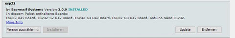
A window opens listing all available packages. To narrow down the list, enter “esp32” in the search field. Then you only get one entry in the list. Install the esp32 package. If the package was already installed, please check whether you have version 2.0.9.
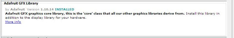
For the display you need two libraries that can be installed via the Arduino library management. This is the library “Adafruit_ILI9341” in version 1.5.10

and the library “Adafruit_GFX” in version 1.10.14.
Two additional libraries are required for the touchscreen. This is “XPT2046_Touchscreen” in version 1.4.0

and “Touchevent” in version 1.3.0

The core of this project is the library “ESP8266Audio” by Earle F. Philhower in version 1.9.7.

This library makes it possible to read, decode and play back various digital audio streams via different output channels. The program memory, the internal RAM, a file system, an SD card, an HTTP stream, or an ICY stream can be used as input. The ICY stream is typically used by Internet radios.
WAV, MOD, MIDI, FLAC, AAC and MP3 files can be decoded. MP3 is required for the web radio. Finally, the output can be in memory, files or I2S.
When all libraries are installed, the sketch can be compiled and uploaded to the hardware.
Danger! Since the sketch consists of numerous parts, it can take a long time to compile, especially the first time. For the ESP32 package and the ESP8266audio library, it is important to use the specified versions because the audio library was programmed very closely to the hardware.
If you want to save yourself the hassle of compiling, you can download the compiled firmware here and upload it directly to the ESP32.
To upload the binary file you need a utility program that can be downloaded free of charge from Espressif.Flash Download Tools
You need to download and unzip the ZIP file. Then you can start the included program flash_download_tool_3.9.5.exe. A window for selecting the controller appears.

Here you select ESP32 as the chip type and Develop as the work mode. The program continues with OK. The tool's working window appears.

Connect the ESP32 to the computer using a USB cable and select the serial port used at the bottom right. In the top line, set the path to the downloaded BIN file for the clock radio. 0x10000 must be entered as the destination address. Select all other settings as shown in the figure. Now you can click on “START”. The upload begins. When everything is finished, the green “IDLE” area changes to blue with the text “FINISH”. The ESP32 now has the firmware for the radio alarm clock and can be put into operation. The compiled BIN file only works with the current version of AZ-Touch.
Installation
When you first start up, there are no preferences yet. Therefore, a connection to the local WiFi cannot be established. An access point with the SSID “radioweckerconf” without a password is started. A corresponding message appears on the display.

A connection to this access point can now be established using, for example, a smartphone. The configuration page can then be accessed in a browser using the address 192.168.4.1.

After rebooting, you should be able to connect to the local WiFi successfully. The current time and date should be shown on the display.

If you tap anywhere on the display, the operating page appears.

There are three sliders for volume, brightness and sleep time. The settings are changed by tapping on the desired position. A special feature applies to the brightness. If set to 0, if the optional LDR is present, the brightness is adjusted to the ambient brightness.
In the fourth line you can see the current radio station. Using the two buttons on the left and right, stations can be selected from the station list.
At the bottom is a row of buttons.
 The radio turns on or off. The display returns to the time display. If the radio was switched on, the radio block with the station name and the metadata (e.g. name of the song currently being played) appears under the time display.
 The sleep time starts. If the radio is not turned on, it will turn on. The display returns to the time display. When the set sleep time has passed, the radio switches off automatically.
 The alarm clock function is switched on or off. The display returns to the time display. If the alarm clock has been switched on, the day of the week and the time when the alarm clock will next be triggered appear at the bottom of the display. If the displayed day of the week and time are correct, the radio will automatically turn on.
 The selected station is adopted as the active station. If the radio is currently switched on, the stream automatically switches to the new station. The display returns to the time display.
 The display returns to the time display.
If there is no activity for 10 seconds, the display automatically returns to the time display. All settings changes are saved in preferences. The operating page is always displayed at full brightness.
Configuration and editing of alarm times and the station list
The configuration page should be accessible via the URL http://radiowecker/.

In the upper part the access data and the NTP server can be changed. The changes will only take effect once the “Save” button has been clicked.
A restart can be triggered using the “Restart” button.
Next are the alarm times. Two alarm times can be set. For each of the alarm times, the days of the week on which the alarm times are to be applied can be selected.
The drop-down list below contains all channels in the channel list. Selectable channels have a black dot in front of the name. In the form below, the data for the selected station is displayed and can be changed. If the “Use” box is not checked, the station cannot be selected in the device. Since some URLs do not work, a new URL should be tested using the “Test” button. Clicking on this button starts playback of the URL on the device. Danger! The radio must be switched on on the device for testing. If playback does not work, it will immediately switch back to the current station and a message will be displayed. If playback is possible, a box with a button will appear. Clicking this button closes the box and ends the test. The current station is played again. The position of the selected station within the station list is displayed in the “Position” input field. By changing this value, the station can be moved to the specified position. Using the “Change” button, the changes for the selected station can be made permanent.
Firmware update via OTA
To update the program, it is not necessary to open the device and connect a USB connection. In the Arduino IDE you should see the following entry under the ports.

You can now upload a sketch via this port. For protection, the password “wakeup update” must be entered when prompted. Since the serial interface cannot be used, messages are shown on the display.

The article is available as a PDF here
Have fun replicating it.


146 comments
Anton Mayr
Tolles Projekt, habe die Teile erhalten, zusammengebaut -super!
Wie komme ich zu den Links der Sender (Österreich)?
kunigunde
kleiner Verbesserung Vorschlag:
Wenn zwar ein Alarm eingestellt, dieser jedoch deaktiviert ist sieht man es nicht.
Um auch dies angezeigt zu bekommen muss in der Datei tft_display.ino die function showNextAlarm(){
….
}
angepasst werden zu:
-————————————
void showNextAlarm(){
char txt100 = "";
uint8_t h,m;
if (clockmode) {
if (alarmday < 8){
h = alarmtime / 60;
m = alarmtime % 60;
sprintf(txt,“Wecker: %s um %i:%02i”,days[alarmday],h,m);
textInBox(0,220,320,20,txt,ALIGNCENTER,false,0xC000,ILI9341_BLACK,1);
}else{
sprintf(txt,“WECKER AUSGESCHALTEN !!!”);
textInBox(0,220,320,20,txt,ALIGNCENTER,false,ILI9341_RED,ILI9341_BLACK,1);
}
}
}
-——————————-
kunigunde
@Bernd-Steffen Großmann
dies steht dir zur Verfügung:
#define ILI9341_BLACK 0×0000 ///< 0, 0, 0
#define ILI9341_NAVY 0×000F ///< 0, 0, 123
#define ILI9341_DARKGREEN 0×03E0 ///< 0, 125, 0
#define ILI9341_DARKCYAN 0×03EF ///< 0, 125, 123
#define ILI9341_MAROON 0×7800 ///< 123, 0, 0
#define ILI9341_PURPLE 0×780F ///< 123, 0, 123
#define ILI9341_OLIVE 0×7BE0 ///< 123, 125, 0
#define ILI9341_LIGHTGREY 0xC618 ///< 198, 195, 198
#define ILI9341_DARKGREY 0×7BEF ///< 123, 125, 123
#define ILI9341_BLUE 0×001F ///< 0, 0, 255
#define ILI9341_GREEN 0×07E0 ///< 0, 255, 0
#define ILI9341_CYAN 0×07FF ///< 0, 255, 255
#define ILI9341_RED 0xF800 ///< 255, 0, 0
#define ILI9341_MAGENTA 0xF81F ///< 255, 0, 255
#define ILI9341_YELLOW 0xFFE0 ///< 255, 255, 0
#define ILI9341_WHITE 0xFFFF ///< 255, 255, 255
#define ILI9341_ORANGE 0xFD20 ///< 255, 165, 0
#define ILI9341_GREENYELLOW 0xAFE5 ///< 173, 255, 41
#define ILI9341_PINK 0xFC18 ///< 255, 130, 198
Du kannst jedoch auch jede andere Farbe einfach selbst erstellen, statt ILI9341_XXXX gibst du dort direkt den Hex wert ein.
um den Hex wert zu bekommen gehts du am besten hier hin (du benötigst den RGB565 Wert unten):
https://barth-dev.de/online/rgb565-color-picker/
kunigunde
@Gerald Lechner
@Dennis
nochmal zum Weckzeit Anzeige Fehler.
Gerald’s korrigierte Version:
sprintf(txt,“Wecker: %s um %i:%02.0i”,days[alarmday],h,m);
Anzeige:
Wecker: Dienstag um 6:1 bzw Wecker Dienstag 6:_
-——————-
meine Version:
sprintf(txt,“Wecker: %s um %i:%02i”,days[alarmday],h,m);
Anzeige:
Wecker: Dienstag um 6:01 bzw Wecker Dienstag 6:00
P.S.: auf Github aktualisiert
Bernd-Steffen Großmann
@kunigunde: Super, besten Dank! Jetzt kann ich alles nach persönlichem Geschmack einstellen. Bleibt nur noch die Frage: welche Farben sind bei dem ILI934-Treiber alle möglich?
@Heiko Janisch: Ich hab jetzt mal einen anderen ESP32 geflasht. Mal sehen, ob die Konnektivitäts-Probleme damit beseitigt sind; der erste ESP hatte schon wieder die Verbindung verloren!? Und: Die Lautsprecher hab ich einfach mit 2-Komp.kleber eingeklebt.
Gerald Lechner
@Konrad: Wenn das Radio über das Symbol mit der Glocke eingeschaltet wird, läuft es bis die Einschlafzeit abgelaufen ist. Über das Lautsprechersymbol kann man es auch vorzeitig abschalten. Um das Radio dauerhaft einzuschalten, darf man nicht das Symbol mit der Glocke sonder muss man das Lautsprechersymbol benutzen.
@Heiko Janisch: Ich habe nur zwei Schrauben verwendet. Oben vorne und unten hinten.
Heiko Janisch
“Heureka – ich habe es!” würde Archimedes jetzt an meiner Stelle sagen. Mit dem Spiegeln der X- und Y-Achse funktioniert nun auch das 2.4" TFT.
Leider stören mich auch noch viele Verbindungsabbrüche im WLAN, obwohl ich eine sehr schnelle Leitung habe und der Abstand zum Router nur ca. 4 Meter beträgt. Wenn es dazu Neuigkeiten gibt, wäre ich für Lösungsansätze sehr dankbar.
@ Gerald Lechner: Vielen Dank für die STL-Dateien. Dazu noch eine Frage: Wie haben Sie die Lautsprecher im Pultgehäuse befestigt? An die hinteren Schrauben kommt man ja fast nicht ran?
kunigunde
@Bernd-Steffen Großmann
Ich habe eine Version auf GitHub hinterlegt bei der sämtliche Farben des Haupt Bildschirms angepasst werden können.
Link:
https://github.com/beabel/radiowecker
Konrad
Hallo Herr Lechner,
Sie haben sich mal wieder selbst übertroffen! Was für ein tolles Projekt! Ein großes Dankeschön.
Ich bin was das Löten speziell bei Platinen angeht nicht der große Könner, aber es hat sich Gott sei Dank in Grenzen gehalten und ich habe es auf Anhieb ohne mich zu “verlöten” geschafft (bei der 2. Variante des Radios bin ich ganz schön an meine Grenzen gekommen).
Zu folgendem kann ich aktuell noch nichts sagen:
1. Das Rückteil muss ich erst noch bei meinem Schwager in “Auftrag” geben.
2. Die Photodiode habe ich noch nicht installiert. Könnte also sein, dass ich da nochmal mich melde.
Meinen kleinen Wünsche:
1. Könnte man kunigunde ’s index Datei auch runterladen? Die Original index Datei hat teilweise kleinere Formatierprobleme in der Darstellung (vermutlich ein CSS Thema).
2. Das mit der Einschlafzeit einstellen ist mir noch nicht klar. Ich hatte Sie Testweise mal auf 5 min eingestellt. Das hat dann auch super geklappt. Aber ich habe das dann nicht mehr abgestellt bekommen. Immer nach 5 Minuten ging es aus; – egal welchen Knopf ich gedrückt habe. Aktuell habe ich einfach auf 60 min eingestellt, – was jetzt nicht so störend ist. Danke für eine Klärung.
Nochmals ein RIESENGROßES Dankeschön.
Konrad
Gerald Lechner
@kunigunde: Eine entsprechede Variante mit der Originalschrift ist am Ende des Blogbeitrags zum Download bereitgestellt.
@Heiko Janisch: Am einfachsten in der Datei tft_display.ino, Funktion onTouchClick(TPoint p) die Werte umkehren p.x = 320 – p.x; und p.y = 240 – p.y;
@Dennis: Danke für den Hinweis. In der Datei tft_display.ino in der Funktion showNextAlarm() muss der Formatstring geändert werden
sprintf(txt,“Wecker: %s um %i:%02.0i”,days[alarmday],h,m);
Dennis
Beim Anzeigen der Weckzeit gibt es eine Fehler wenn bei den Minuten 00-09 ausgewählt wird. Z.B. es wird 6:00 Uhr als Weckzeit eingestellt, dann wird 6:0 angezeigt, bei 6:09 Uhr als Weckzeit wird 6:9 angezeigt, erst bei einer Weckzeit 6:10 Uhr und mehr wird die Zeit richtig angezeigt. Der Fehler tritt auch bei allen anderen Möglichkeiten auf (1:09, 5:09 usw.)
Heiko Janisch
Die Ursache habe ich gefunden, die X und Y Achsen sind spiegelverkehrt. Damit reagiert das 2.4 Touch immer diagonal gespiegelt. Damit stellt sich die Frage, wo muss ich im Code welche Parameter ändern?
kunigunde
@Gerald Lechner
Ich habe das Problem mit den Wunschfarben der Uhrzeit gelöst.
1. es ist nur eine einzige ziffern.ino nötig
2. die Farbe kann an einer einzigen Stelle angepasst werden
Dazu werden jeweils schwarz/weiße Bitmaps (01234567890:) benötigt (schwarz = Hintergrund)
Ich stelle meine unter dem Download- Link mit zur Verfügung, jedoch habe ich zum test jetzt nur eine Standard Schriftart benutzt.
was man am Programm tun muss ist:
1. ==> 01_ziffern.ino austauschen
2. dies:
tft.drawRGBBitmap(30+i*55,30,ziffern_rot[z],50,70);
ändern zu:
tft.drawBitmap(30+i*55,30,ziffern_rot[z],50,70,ILI9341_BLUE,ILI9341_BLACK);
Download Link:
01_ziffern.ino:
https://github.com/beabel/radiowecker/blob/main/01_ziffern.ino
tft_display.ino:
https://github.com/beabel/radiowecker/blob/main/tft_display.ino
Bernd-Steffen Großmann
@Harald – Ich habe ebenfalls Probleme mit der Stabilität der WLAN-Verbindung (connection lost), obwohl der Router (Fr.Box 7490) keine 3 m entfernt auf der selben Ebene steht. Mir scheint, dass der ESP32 WROOM (von AZ-Del.) Stabilitäts- und Probleme mit dem Speichern der Konfigurationsdaten hat. Heute morgen waren sogar die WLAN-Daten komplett “weg”! Ich musste sie über die Start-Konfiguration (192.168.4.1) neu eingeben. Ich werde mal einen anderen ESP32 ausprobieren.
@Gerald Lechner: Zitat: “Der LDR wird zwischen GND und GPIO34 angeschlossen. GPIO34 wird über einen Pullup Widerstand von 10kOhm mit 3.3V verbunden.” Zitat Ende.
Laut Konfiguration (//pin to be used for light sensor , #define LDR 36), Stromlauf- und Bestückungsplan muss der LDR an GPIO36 (A0). Und: Mein LDR (der KY-018 – aus dem 35-in1 Sensor-Kit von AZ-Del.) hat bereits einen 10kOhm Widerstand von S nach +!
Ich habe gerade auch die neue Ziffern01.ino eingespielt und jetzt zeigt das Display schöne blaue Ziffern bei der Zeit (passt sehr gut zum blauen Gehäuse), nur das Datum ist weiter in roter Schrift. Wenns nicht zu viel Aufwand macht: wie kann man das ändern?
Gerald Lechner
@Heiko Janisch: Es hat auch ein 2.4 Zoll Display gegeben, bei dem eine der beiden Achsen der Touchfolie um 180° gedreht war. Erkenntlich war das an einer gelben Stiftleiste. In dem Fall müsste das bei der verarbeitung der Events berücksichtigt werden. Von einer unterschiedlichen Firmwarebhabe ich nichts gehört. Es wird bei beiden Displays der Controller XPT2046 verwendet.
@kunigunde: Das mit den eingefärbten schwarz/weiß Bitmaps finde ich eine hervorragende Idee. Es erfordert ein wenig Programmänderung. Ich werde eine entsprechende Version erstellen und zum Download zur Verfügung stellen.
kunigunde
@Gerald Lechner
@Harald Valeri
Bezugnehmend auf die Wunschfarben der Ziffern,
habe ich eine Frage? Ist es möglich die Bitmaps der ziffern als schwarz/weiß zu integrieren, und dann statt drawRGBBitmap die drawBitmap funktion zu nutzen, bei welcher man die Farbe anpassen kann?
drawRGBBitmap(int16_t x, int16_t y, uint16_t *pcolors, int16_t w, int16_t h);
vs.
drawBitmap(int16_t x, int16_t y, uint8_t *bitmap, int16_t w, int16_t h, uint16_t color)
Heiko Janisch
Danke für den Hinweis. Das AZ-Touch Board ist die Version 01-03, sollte also aktuell sein.
Die Pin-Definitionen habe ich mit der Hardware überprüft, das passt auch. Wie schon geschrieben, funktionieren beim 2.8 Zoll Display und Touch tadellos. Beim 2.4 funktioniert das Display auch ohne Fehler, nur die Touch-Funktion ist fehlerbehaftet. Der Druckpunkt auf dem Display löst ganz andere Funktionen aus. In der Anleitung zum AZ-Touch MOD wird ein Beispiel zum Testen der Funktionalität, ein einfaches Code-Schloss, aufgeführt. Dabei benötigt jedes TFT (2.4 und 2.8 Zoll) jeweils einen eigene Firmware für den ESP32. Insofern denke ich, dass es einen Unterschied bei der Touch-Funktionalität zwischen beiden TFT-Displays gibt. Ich weiß nur nicht, wo ich ansetzen soll.
Gerald Lechner
@Peter Lauber: Es gibt da noch einen weiterern Fehler, der den angezeigten Fehler auslöst. Überprüfen Sie die Anzeige auf weitere Fehler.
@Manfred: Ich habe dieses Problem fallweise auch gesehen, hab aber leider auch keine Idee wodurch diese Aussetzer verursacht werden.
@Harald Valeri: Die Ziffern sind Bitmaps die in der Datei 01_ziffern.ino als Array definiert werden. Ich werde Varianten der Datei für die Faben blau, grün und gelb erstellen und zum Download anbieten. Den Download werden Sie am Ende des Blog-Beitrags finden.
@Heiko: Das 2.4 Zoll Display sollte ohne Änderung funktionieren. Es könnte aber sein, dass Sie eine ältere Variante des AZ-Touch haben, der eine Abweichende Belegung für den Touch Interrupt hatte. Überprüfen Sie die Pin-Definitionen am Beginn der Datei tft_display.ino
@Peter: Der LDR wird zwischen GND und GPIO34 angeschlossen. GPIO34 wird über einen Pullup Widerstand von 10kOhm mit 3.3V verbunden.
Peter
Der Schaltplan beinhaltet 3 Widerstände.
R1 = 470 kOhm
R2 = LDR03 selbst?
R3 (Pin 1 an LDR und auch an Pin 3).
Es ist unklar (nicht lesbar), um welchen Widerstand es sich handelt und wo er auf der Platine montiert werden kann.
Könnten Sie das bitte klären?
Heiko
Ein wirklich tolles Projekt, was nach Fertigstellung meinen Schreibtisch im HomeOffice bereichern wird. Mit dem 2,8 Zoll Display funktioniert es tadellos. Ich habe aber auch noch ein 2,4 Zoll Display und würde dieses gerne verwenden. Die Anzeige funktioniert hier auch einwandfrei, nur die Touch-Bedienung haut nicht hin. Wo im Sketch habe ich die Möglichkeit, das 2,4" Touch zu konfigurieren bzw. auszuwählen?
Harald Valeri
Hallo Herr Lechner,
wie kann ich die Uhrzeit-Ziffer-Farbe ändern? Von aktuell Rot auf z.B. Grün oder Blau?
Für einen Hinweis wäre wäre ich dankbar.
Schöne Grüße
Harald
Manfred
Habe das Paket bestellt und zusammengebaut und es hat auf anhieb funktioniert.
Leider läuft das Radio nicht lange und es gibt Aussetzer bis zum connection lost …
was kann das sein.
habe ein stabiles Internet und Plan
lg. Manfred
Peter Lauber
Ich erhalte beim Kompilieren die Fehlermeldung "expected initializer bevfore “[” Token" aus der 01-zeichen.ino Markiert ist die Zeile const uint16_t ziffern_rot PROGMEM 11 3500 = {
Wo steckt der Fehler?
Wolfgang Schneider
Das set ist heute angekommen, leider fehlt ein MAX98357A – es war nur ein Tütchen in der Box. Mal sehen, wie schnell die Nachlieferung kommt.
die beiden Lautsprecher lagen lose und unverpackt in der Box, bin gespannt, ob die noch funktionieren, es sind erst mal keine offensichtlichen Schäden erkennbar.
An den Lautsprechern sind schöne JST Steckerchen angebracht, leider liegen dem MAX98357A nur Schraubportale bei. Wäre eigentlich schöner gewesen, wenn man dafür eine passende JST Buchse beigelegt hätte. (Ich muss mal schauen, ob ich noch welche rumliegen hab).
Volker
Hallo, kann mir jemand sagen, wie das TFT-Display auf die Platine kommt? Lötet man es direkt darauf? Wenn ja, würde es mich wundern, denn man bekommt zumindest bei meiner eigenartigen Produktlieferung die Display-Pins weder auf der einen Seite noch auf der anderen Seite der Platine wegen der dort bereits aufgelöteten Bauelemente in die vorgesehenen Lötstellen.
Jakub
Das Set ist heute angekommen und ich wollte es gleich mit meinem Sohn aufbauen.
Die Anleitung finde ich etwas dürftig, auf jeden Fall könnten die Bilder eine höhere Auflösung haben.
In das mitgelieferte Wandgehäuse passen nicht alle Teile rein, es muss also das größere gedruckt werden.
Ich habe das LDR Modul mitbestellt, würde es lieber mit 1-2 Schrauben befestigen, als mit dem doppelseitigen Klebeband.
Die DC Buchse war im Shop leider nicht lieferbar. Die 10 Stück bei Amazon sind mir zu viel.
Die Lautsprecher haben konfektionierte Zuleitungen, die Stecker passen nicht zu den Verstärkerplatinen und müssen abgeschnitten werden, schade.
Den 470kR Wiederstand hätte ich gern im Set gesehen.
Eine nette Option wäre ein Batteriebetrieb.
Mit einer 18650 kommt man da schon recht weit.
Der Eindruck ist allerdings ziemlich positiv.
Wenn alles zum Schluss funktioniert kann ich das Set weiterempfehlen.
Gerald Lechner
@Thomas: In der Datei tft_display.ino kannn die Darstellung in Zeile 233 mit tft.setRotation(1); um 180 Grad gedreht werden. Das Speichern und Ändern der Sender funktioniert bei mir wie es soll. Eventuell ist die Senderliste durcheinandergekommen. Mit dem Knopf “Senderliste zurücksetzen” erhalten Sie wieder die Defaultliste.
Gerald Lechner
@Gottfried Karner: Das wäre grundsätzlich möglich, stellt aber einen erheblichen Programmieraufwand dar. Die Anpassung müsste in der Datei tft_display.ino erfolgen. allerdings müsste dann die Darstellung des aktiven Senders ebenfalls angepasst werden.
Gerald Lechner
@Manfred: Sie haben eventuell eine alte version von AZ-Touch bei der die Hintergrundbeleuchtung mit High eingeschaltet werden muss. In diesem Fall müssen Sie den Sketch selber kompilieren. Überprüfen Sie vor dem Kompilieren in der Datei tft_display.ino die Pin Zuordnung. LED_ON müssen Sie in diesem Fall auf 1 setzen.
Gerald Lechner
@Bernd-Steffen Großmann: Wenn Sie die Datei 01_ziffern.ino mit der aus dem folgenden Link austauschen wird die “3” richtig dargestellt.
https://drive.google.com/file/d/1v3vGvkQTqI4Wcixp4Wk12-nT8bRs2jLc/view?usp=share_link
Manfred
Hallo
Habe das .bin heruntergeladen und lt. Anleitung geflasht. Hat auch ohne Fehler funktioniert.
leider bleibt das Display schwarz …
passen die Einstellungen am falscher ? 0×10000 ?
bitte um Info
lg. Manfred
Bernd-Steffen Großmann
Noch eine kurze Ergänzung: nachdem ich heute die Schaltung entsprechend dem Verdrahtungsplan aufgebaut habe, funktioniert jetzt fast alles wie beschrieben, außer einigen Sendern: wie z.B. Hessen, u.a. Da muss ich noch mal im Netz nach den richtigen URLs suchen, und es fehlt ja auch noch der (für Senioren wie mich wichtige) WDR4 ;0)
Eins war mir auch noch aufgefallen: die Dreien in der Uhrzeit scheinen auf dem Kopf zu stehen, haben den großen Bogen oben und den kleinen unten. Das sieht etwas „schräg“ aus. Kann man das korrigieren? Wenn ja, wie? Ansonsten alles super! Noch mal besten Dank für tolle Arbeit und die super Anleitung! Mfg
Gerald Lechner
@Werner: Ich habe es mit mehreren Browsern getestet und keine Probleme gehabt. Die ZIP Datei enthält nur Textdateien.
Gerald Lechner
@Michael:
@Bernd-Steffen Großmann:
Danke für den Hinweis. Da ist mir leider ein Fehler passiert. Ich habe den Schaltplan korrigiert im Web und im PDF.
@Bernd-Burkhard BBB Borys:
Erstens muss ich darauf hinweisen, dass der Schaltplan einen Fehler enthielt, den ich korrigiert habe. Und nun zur Frage. Gain auf GND bedeutet 12dB Verstärkung. Die Lautstärke kann über die Software geregelt werden. An Vin wäre die Verstärkung 6dB. Der Anschluss SD dient zur Auswahl, welcher Kanal ausgegeben werden soll an Vin = linker Kanal, über 470 kOhm an Vin = rechter Kanal.
@Wolfgang Schneider:
Ich nutze ein Steckernetzteil mit 9V und 300mA.
@neil:
You are right, there was an error in the schematic. I have corrected it. You see now the correct schematicon web page and in the PDF.
Bernd-Steffen Großmann
Hallo Herr Lechner, sehr schönes Projekt. Jetzt kann ich endlich meinen doch recht einfachen Testaufbau eines Webradio mit Display und Touch-Bedienung ausstatten und das Az-Touch-Teil, was bisher nur mit Testsoftware ausgestattet war, einer sinnvollen Anwendung zuführen. Die Programmierung vom ESP32 ging mit der Arduino IDE problemlos, nachdem ich mit dem direkten Flashen des bin-Files keinen Erfolg hatte. Es wurde vom Py-Flasher ein Fehler im Header angezeigt!? Das Einrichten mit den WLAN-Daten und der Konfiguration funktionierte auch einwandfrei. Jetzt bin ich an der Tonausgabe-Seite dran und stolpere über einige Unstimmigkeiten zwischen dem Schaltplan und der Verdrahtung. Im Schaltplan geht der DIN-Anschluss vom MAX-IC an GPIO32 und in der Verdrahtung an GPIO33? Und auch der SD-Pin geht in der Schaltung an GPIO32 und in der Verdrahtung an 5V? Was ist richtig? Mit freundlichen Grüßen, Bernd-Steffen Großmann
Gottfried Karner
Wunderbares Projekt und perfekt dokumentiert.
Möchte ich sofort nachbauen.
Da ich nachts ohne Brille nicht gut sehe, eine Anfrage. Könnte man ein etwas größeres Display mit analoger Uhr in das Projekt integrieren?
mfg G.K.
neil
Hello
Is there not an error in your circuit diagram, it shows the SD pin (and resistor connected to the DIM line and not +5vs.
The board layout looks correct.
Thanks
Neil
kunigunde
Ich habe mir die Konfiguration’s Seite ein wenig moderner gestaltet.
Dazu habe ich die index.h bearbeitet.
[code]
//html for web pages
const char OPTION_entry[] PROGMEM =
“<option value=‘%i’ %s>%s %s”;
const char MAIN_page[] PROGMEM = R"=(
Web Radiowecker WLAN / WIFI: SSID:<link href = “https://code.jquery.com/ui/1.10.4/themes/ui-lightness/jquery-ui.css” rel = "stylesheet">
<script src = “https://ajax.googleapis.com/ajax/libs/jquery/3.5.1/jquery.min.js”>
<br /> $(function() {<br /> $(document).ready(getAll);<br /> $(“#btn_save”).click(saveSSID);<br /> $(“#btn_reset”).click(restartHost);<br /> $(“#btn_test”).click(testStation);<br /> $(“#btn_updt”).click(updateStation);<br /> $(“#btn_restore”).click(restoreStations);<br /> $(“#btn_savealarm”).click(setAlarms);<br /> $(“#btn_cancelalarm”).click(getAlarms);<br /> $(“#stationlist”).change(getStation);<br /> });</p> <p>function getAll() {<br /> getSSID();<br /> getStationList();<br /> getAlarms();<br /> }</p> <p>function getStationList() {<br /> $.ajax({<br /> type:“<span class="caps">GET</span>”,<br /> url:“/cmd/stations”,<br /> data:{},<br /> success: function(data){<br /> $(“#stationlist”).html(data);<br /> getStation();<br /> }<br /> });<br /> }</p> <p>function getStation() {<br /> $.ajax({<br /> type:“<span class="caps">GET</span>”,url:“/cmd/getstation”,<br /> data:{"stationid":$(“#stationlist”).val()},<br /> success: function(data){<br /> const parts = data.split(“\n”);<br /> $(“#name_input”).val(parts<sup class="footnote" id="fnr0"><a href="#fn0">0</a></sup>);<br /> $(“#url_input”).val(parts<sup class="footnote" id="fnr1"><a href="#fn1">1</a></sup>);<br /> $(“#enable_input”).prop(“checked”,(parts<sup class="footnote" id="fnr2"><a href="#fn2">2</a></sup> == 1));<br /> $(“#pos_input”).val(parts<sup class="footnote" id="fnr3"><a href="#fn3">3</a></sup>);<br /> }<br /> });<br /> }</p> <p>function updateStation() {<br /> const checked = $(“#enable_input”).prop(“checked”)?1:0;<br /> $.ajax({<br /> type:“<span class="caps">GET</span>”,<br /> url:“/cmd/setstation”,<br /> data:{"stationid":$(“#stationlist”).val(),<br /> <a href="">name</a>$(“#name_input”).val(),<br /> <a href="">url</a>$(“#url_input”).val(),<br /> <a href="checked">enabled</a>,<br /> <a href="">position</a>$(“#pos_input”).val()},<br /> success: function(data){<br /> const n = ( $(“#enable_input”).prop(“checked”))?"&#x25cf; “:”&#x2002; "<br /> $( “#stationlist option:selected” ).html(n + $(“#name_input”).val());<br /> alert(data);<br /> getStationList();<br /> }<br /> });<br /> }</p> <p>function restoreStations() {<br /> $.ajax({<br /> type:“<span class="caps">GET</span>”,<br /> url:“/cmd/restorestations”,<br /> data:{},<br /> success: function(data){<br /> getStationList();<br /> }<br /> });<br /> }</p> <p>function testStation() {<br /> const checked = $(“#enable_input”).prop(“checked”)?1:0;<br /> $.ajax({<br /> type:“<span class="caps">GET</span>”,<br /> url:“/cmd/teststation”,<br /> data:{"url":$(“#url_input”).val()},<br /> success: function(data){<br /> alert(“Mit OK beenden Sie den Test”);<br /> endTest();<br /> },<br /> error: function() {<br /> alert(“<span class="caps">ERROR</span>”);<br /> }<br /> });<br /> }</p> <p>function endTest() {<br /> const checked = $(“#enable_input”).prop(“checked”)?1:0;<br /> $.ajax({<br /> type:“<span class="caps">GET</span>”,<br /> url:“/cmd/endtest”,<br /> data:{},<br /> success: function(data){<br /> }<br /> });<br /> }</p> <p>function getSSID() {<br /> $.ajax({<br /> type:“<span class="caps">GET</span>”,<br /> url:“/cmd/getaccess”,<br /> data:{},<br /> success: function(data){<br /> const parts = data.split(“\n”);<br /> $(“#ssid_input”).val(parts<sup class="footnote" id="fnr0"><a href="#fn0">0</a></sup>);<br /> $(“#pkey_input”).val(parts<sup class="footnote" id="fnr1"><a href="#fn1">1</a></sup>);<br /> $(“#ntp_input”).val(parts<sup class="footnote" id="fnr2"><a href="#fn2">2</a></sup>);<br /> }<br /> });<br /> }</p> <p>function getAlarms() {<br /> $.ajax({<br /> type:“<span class="caps">GET</span>”,<br /> url:“/cmd/getalarms”,<br /> data:{},<br /> success: function(data){<br /> const parts = data.split(“\n”);<br /> for (var i = 0; i < 16; i++) {<br /> if ((i0) || (i8)) {<br /> $(“#al”<ins>i).val(parts[i]);<br /> } else {<br /> if (parts[i]==‘1’) {<br /> $(“#al”</ins>i).prop(‘checked’,true);<br /> } else {<br /> $(“#al”+i).prop(‘checked’,false);<br /> }<br /> }<br /> }<br /> }<br /> });<br /> }</p> <p>function saveSSID() {<br /> $.ajax({<br /> type:“<span class="caps">GET</span>”,<br /> url:“/cmd/setaccess”,<br /> data:{"ssid":$(“#ssid_input”).val(),<a href="">pkey</a>$(“#pkey_input”).val(),<a href="">ntp</a>$(“#ntp_input”).val()},<br /> success: function(data){<br /> alert(data);<br /> }<br /> });<br /> }</p> <p>function setAlarms() {<br /> const vals = new Object();<br /> for (var i = 0; i < 16; i++) {<br /> if ((i == 0) || (i == 8)) {<br /> vals[’al’+i] = $(“#al”<ins>i).val();<br /> } else {<br /> vals[‘al’</ins>i] = $(“#al”+i).prop(“checked”)?‘1’:‘0’;<br /> }<br /> }</p> $.ajax({ type:“<span class="caps">GET</span>”, url:“/cmd/setalarms”, data:vals, success: function(data){ alert(data); } }); <p>}</p> <p>function restartHost() {<br /> $.ajax({<br /> type:“<span class="caps">POST</span>”,<br /> url:“/cmd/restart”,<br /> data:{},<br /> });<br /> }<br />
<br /> body {<br /> width:300px;<br /> background-color: silver;<br /> }<br /> label { <br /> display: inline-block;<br /> margin-top: 5px;<br /> width: 100%;<br /> float: left; <br /> }<br /> button {<br /> width:45%;<br /> margin: 5px;<br /> height: 2.0em; <br /> }<br /> input {<br /> width:100%;<br /> }<br /> /* einzelnen Abschnitte moderner */<br /> fieldset {<br /> background-color: white;<br /> border: 2px solid orange;<br /> margin: 0 auto;<br /> margin-top: 20px;<br /> }<br /> legend {<br /> color: white;<br /> background-color: orange;<br /> width: 100%;<br /> text-align: center;<br /> }</p> <p>/* checkboxen Wochentage als “Button” */<br /> .categorie{<br /> background-color: white;<br /> overflow: hidden;<br /> float: left;<br /> }<br /> .categorie label {<br /> float: left;<br /> line-height: 2.0em;<br /> width: 2.0em; <br /> height: 2.0em;<br /> margin: 2px;<br /> }<br /> .categorie label span {<br /> text-align: center;<br /> padding: 2px 0;<br /> display: block;<br /> cursor: pointer;<br /> border: 1px solid silver;<br /> }<br /> .categorie label input {<br /> position: absolute;<br /> display: none;<br /> }<br /> .categorie input:checked + span {<br /> color: white; <br /> }<br /> .categorie input:checked + span{background-color: #82D44E;}</p>
PKEY:
NTP:
Speichern Neustart
Senderliste Reset Wecker: Weckzeit 1:
Mo Di Mi Do Fr Sa So
Weckzeit 2:
Mo Di Mi Do Fr Sa So
Speichern Rückgängig Radio Stationen: Liste:
Name:
URL:
Verwenden:
Position:
Testen Ändern
)=";
//*****************************************************************************************************************
Internet Radio SSID: PKEY: Neustartconst char CONFIG_page[] PROGMEM = R"=(
<!DOCTYPE html>
<br /> body {<br /> width:300px;<br /> font-family:arial;<br /> }<br /> button {<br /> width:110px;<br /> background-color:silver;<br /> border-radius:10px;<br /> }<br /> .theme {<br /> background-color:cadetblue;<br /> padding:10px;<br /> border-radius: 10px;<br /> border: 2px solid silver;<br /> }<br /> .confpane {<br /> width:280px;<br /> height:75px;<br /> }<br /> .txtinput {<br /> position:absolute;<br /> left:90px;<br /> width:200px;<br /> }<br /> .label {<br /> color:white;<br /> font-family:arial;<br /> }</p>
)=";
[/code]
Bild:
https://drive.google.com/file/d/19i58HMTt3gapNuI2ZW17agT1Tr4vgEBl/view?usp=sharing
P.S.: Ihr habt einen Schreibfehler hier über dem Kommentarfeld:
“Nächser Beitrag” da ist das t verloren gegangen
Thomas
Hallo. Ich habe ein Problem mit dem Touch, dieser ist bei mir um 180° gedreht. Wie kann ich das ändern?
Zudem kann ich über das Web-Interface neue Sender nicht richtig zuordnen, 2 funktionieren, beim 3. wird der erste wieder überschrieben. Ich kann die Stationsnummer zwar angeben, aber es wird nicht nachvollziehbar auf den ersten 3 Stationen gespeichert, teils auch Station 1 überschrieben, obwohl ich Station 3 ausgewählt habe.
Werner
Hallo Herr Lechner. Die “radiowecker.zip” scheint wohl einen virus zu enthalten … zumindest blockt der download mit der Meldung “Konnte nicht herunter geladen werden – Virus erkannt” beim ende-browser sowohl ach beim google chrome.
Wolfgang Schneider
Wie muss das 9V Netzteil ausgelegt werden? Reicht ein 1A Netzteil ?
Michael Kirk
Hallo,
Kompliment, ein wirklich tolles Projekt!
Ich habe gerade das Set bestellt und freue mich schon aufs Bauen.
Vorher habe ich allerdings versucht die Toolchain zu erstellen.
Schliesslich nützt das schönste Projekt nichts, wenn die Software nicht läuft.
Man sollte sich schon genau an die Versionshinweise zu den verwendeten
Bibliotheken halten, sonst klappt das Erstellen nicht.
Aber das ist ja hervorragend dokumentiert.
Keinen Hinweis habe zur Einstellung für das Board gefunden.
Im Kit enhalten ist das “ESP-32 Dev Kit C V4”.
Das Kompilieren klappt mit dem universalen “ESP32 Dev Module”
und dem “ESP32C3 Dev Modul”.
Das STL-File für das Pult-Gehäuse ist natürlich das Sahnehäubchen.
Aber eben mit dem Äusseren hadere ich ein Bischen.
Versteht mich nicht falsch, dies soll keine Kritik sein.
Aber eine Schönheit ist die Kombination aus Gehäuse
und Display-Case wahrlich nicht.
Und wenn man es nicht gerade als Küchenradio plant,
wäre Weiss auch nicht die Farbe meiner Wahl.
Vielleicht gibt es ja einmal Alternativen zum originalen Display-Gehäuse.
Oder jemand erklärt, wie man ohne Paintbrush-Equipment,
dem weissen Gehäuse eine neue Farbe gibt.
Aber das ist wohl meine persönliche Zukunftmusik.
Wir werden sehen, was da noch kommt.
Danke, für dieses wunderbare, detaillierte Projekt.
Michael
Bernd-Burkhard BBB Borys
Ich hätte gerne eine eigene Anwendung mit ESP32, den Verstärkern und Lautsprechern gebaut, aber ich verstehe den Schaltplan nicht. Wieso ist GAIN bei einem Verstärker an GND, beim anderen an VIN angeschlossen und DIN einmal direkt an SD, das andere Mal über einen Widerstand?
Michael
super projekt,
es sieht für mich nur so aus, als ob sich in der schaltplan zeichnung, ein fehler ist, der R1 ist dort falsch angeschlossen, die “verdrahtung” auf dem lochraster dagegen ist richtig.
Hannes
Hi, I tried to download the source files – Windows Defender has found a virus in the zip file. Can you confirm this?
Ian
Can you produce a PDF in English, please?