This post is also available as PDF document.
I recently shown that ESP32 and ESP8266 can send emails independently in a series of contributions (Part 1, Part 2). This requires an email account with a provider like Gmail, which provides a corresponding interface. In this and three other posts, I present four other options for messaging with various circuits. I start today Ifttt. This is the acronym for If this that that. Behind this name is a web portal that provides various services. Among other things, sending emails, triggered by a post from an ESP32 or ESP8266. To do this, we need an account at IFTTT. You can create two applications free of charge per account. In this episode, I describe how this works
Micropython on the ESP32 and ESP8266
today
Ifttt messages from ESP32 and ESP8266
Today's circuit represents a person who can count people who enter a hall or a room through ultrasound. I attached the sensor, an HC-SR04, so that a distance of approx. 30 cm results up to the passing person. The next obstacle should then have a distance of one meter or more. The limit values can of course be adapted to the existing local conditions in the program. The counting process happens when the person leaves the sound cone. A hysteresis, i.e. an exclusion area of possible distances, ensures that multiple stories are prevented. The controller is triggered if a distance of less than 30 cm is measured. Only when the sound path is more than one meter is the counter increased by one.

Figure 1: attach the sensor
By specifying a counting value limit, it can be controlled when the controller should trigger the IFTTT application. A short time later, the mail then arrives in the specified account.
Hardware
Each of the listed controller types can basically be used, at least in this article. When using a BME280, however, the ESP8266 is eliminated due to the lack of storage space. That's why I used an SHT21 for the temperature measurement here. Another reason for this decision is that the building block, as well as the display, can be controlled via the I2C bus.
In order to be able to view the condition of the circuit at any time directly on site, I donated a small display to the ESP. The flash key can be used to demolish the program, for example, actuators have to be switched off safely, such as the LED. The ESP8266 D1 Mini has to be donated to an extra key module because it does not have a flash button himself.
|
1 |
D1 Mini Nodemcu with ESP8266-12F WLAN module or D1 Mini V3 Nodemcu with ESP8266-12F or Nodemcu Lua Amica Module V2 ESP8266 ESP-12F WiFi or Nodemcu Lua Lolin V3 Module ESP8266 ESP-12F WIFI or ESP32 Dev Kit C V4 unplacerated or |
|
1 |
|
|
1 |
LED, for example red |
|
1 |
Resistance 330 Ω |
|
1 |
Resistance 1.0 kΩ |
|
1 |
Resistance 2.2 kΩ |
|
2 |
|
|
1 |
|
|
various |
Jumper Wire cable 3 x 40 pcs. 20 cm M2M / F2M / F2F each possibly too |
|
optional |
So that slots for the cables are still free next to the controller, I have put two Breadboards together with a power rail in between.

Figure 2: Remand meter with ultrasound - ESP8266

Figure 3: Remand meter with ultrasound - ESP32
Finally, the circuit diagrams for ESP32 and ESP8266 are now coming to the hardware.

Figure 4: circuit for ESP32

Figure 5: circuit for ESP8266
The software
For flashing and the programming of the ESP32:
Thonny or
Used firmware for the ESP32:
Used firmware for the ESP8266:
The micropython programs for the project:
SSD1306.PY Hardware driver for the OLED display
oled.py API for the OLED display
sht21.py Driver for the SHT21 module
urequests.py Driver module for HTTP operation
ifttt.py Demo program for sending e-mail
Micropython - Language - Modules and Programs
To install Thonny you will find one here Detailed instructions (English version). There is also a description of how that Micropython firmware (As of 18.06.2022) on the ESP chip burned becomes.
Micropython is an interpreter language. The main difference to the Arduino IDE, where you always flash entire programs, is that you only have to flash the Micropython firmware once on the ESP32 so that the controller understands micropython instructions. You can use Thonny, µpycraft or ESPTOOL.PY. For Thonny I have the process here described.
As soon as the firmware has flashed, you can easily talk to your controller in a dialogue, test individual commands and see the answer immediately without having to compile and transmit an entire program beforehand. That is exactly what bothers me on the Arduino IDE. You simply save an enormous time if you can check simple tests of the syntax and hardware to trying out and refining functions and entire program parts via the command line before knitting a program from it. For this purpose, I always like to create small test programs. As a kind of macro, they summarize recurring commands. Whole applications then develop from such program fragments.
Autostart
If the program is to start autonomously by switching on the controller, copy the program text into a newly created blank tile. Save this file under boot.py in WorkSpace and upload it to the ESP chip. The program starts automatically the next time the reset or switching on.
Test programs
Programs from the current editor window in the Thonny-IDE are started manually via the F5 button. This can be done faster than the mouse click on the start button, or via the menu run. Only the modules used in the program must be in the flash of the ESP32.
In between, Arduino id again?
Should you later use the controller together with the Arduino IDE, just flash the program in the usual way. However, the ESP32/ESP8266 then forgot that it has ever spoken Micropython. Conversely, any espressif chip that contains a compiled program from the Arduino IDE or AT-Firmware or Lua or ... can be easily provided with the micropython firmware. The process is always like here described.
Setting up an ifttt account
Follow the link to iftt.com and click on Get started top right.

Figure 6: IFTTT HOOTS OF THE © IFFTTT.com
I don't want to register via a Google account but with my email address- Sign up.
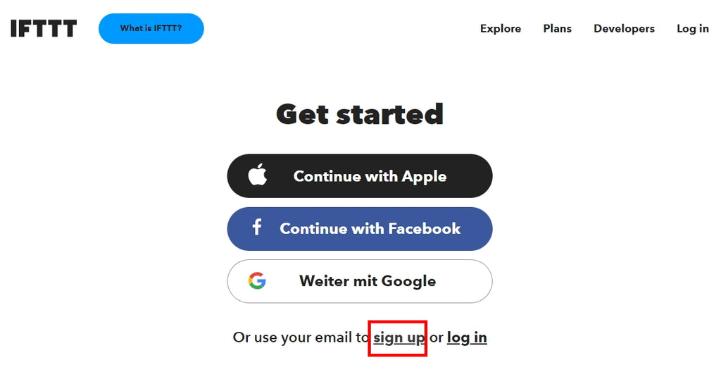
Figure 7: Sign up - Register or register © ifttt.com
Register with email address and a password. It should not The one with which you log in on the mail server. Watch out! The password is only entered once and not verified!

Figure 8: Register © ifttt.com

Figure 9: Optional - download cell phone app © ifttt.com
You have to click at least one of the fields, otherwise it won't go on.

Figure 10: At least one field must be marked © ifttt.com
We do not need full access for our purpose, so - - Not now.

Figure 11: We don't want a Pro account © ifttt.com
Now scroll all the way down - Get Startet

Figure 12: Get Started - Let's get started © ifttt.com
Create an application
We are now creating an applet in our account. Start on the main page Creator.

Figure 13: We start with Create © ifttt.com
First, a trigger, i.e. a trigger, must be defined. click on Add.

Figure 14: We create a trigger © ifttt.com
Give webhook In the search field and then click on the symbol Webhooks.

Figure 15: A webhook is required © ifttt.com
We will send a web request, check the middle field.

Figure 16: Receive A webrequest © ifttt.com
Enter a name for the app and click on Create Trigger.

Figure 17: Generate trigger © ifttt.com
This completes the production of the web hook. Click now That and write e-mail in the search field. Then click on the left symbol - E-mail.

Figure 18: Select a service © ifttt.com
Now connect the service to the trigger - Connect.

Figure 19: Connect service © ifttt.com
Next, the recipient address of the emails is entered. IFTTT sends an email to this account with a PIN that needs to be entered in the next field.
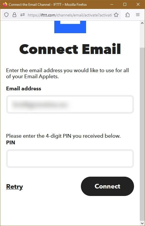
Figure 20: Specify mail receiver © ifttt.com
Take a look in the mail account. An email from ifttt should have arrived there. Transfer the PIN into the form and click on Connect.

Figure 21: Open the mailbox and transfer PIN
Now the subject and the text of the mail are edited - Create action.

Figure 22: Edit content © ifttt.com
With Continy Get to the next page with the overview of the app.

Figure 23: Summary © ifttt.com

Figure 24: Confirmation © ifttt.com
Go up now Maker_Webhooks - Documentation.

Figure 25: For documentation © ifttt.com
On this page you will find the 22-digit API key that you should write down or better copy, because you need it later. Fill out the fields in the form and click on Test ITto send a test email.

Figure 26: Send test email © ifttt.com
Did you get the email?
The program
The connections on the ESP32 are chosen so that the numbers also apply to the ESP8266. The program works for both controller families without changes. It starts with a translation table for the ESP8266. This family likes to annoy users with constant restarts. Therefore, after flashing the firmware, the first thing web "to be killed.
 # ifttt.py
 #
 # Pintranslator for ESP8266 boards
 # Lua-Pins D0 D1 D2 D3 D4 D5 D6 D7 D8
 # ESP8266 Pins 16 5 4 0 2 14 12 13 15
 # SC SD T
 #
 # After flashing the firmware on the ESP8266:
 # Import WebRepl_Setup
 #> D FUR DISABLE
 # Then RST; Restart!
Then we do the import business. From machine we get the classes Pin code and Softi2c, from time the function sleep. Timeout is a self-made module that contains three non-blocking software timers. A function is returned from the functions, a so -called Closure. By taping everything from the module into the global name room, I can later access the functions as if it had been declared directly in the program, i.e. without the usual objectPrefix.
The class SHT21 serves the SHT21 platinum, the OLED class provides an API for the display. You need the class SSD1306, why the file SSD1306.PY must also be uploaded to the flash of the controller. Because the module with the ESP8266 urequest is not included in the kernel, this must also be uploaded. The ESP32 kernel already contains the module. It is used to send and receive HTML packages. We need to connect to the local network Network. sys Gives us ways to query the controller type and leave the program in an orderly manner.
 From machine import Pin code, Softi2c
 From time import sleep
 From time-out import *
 From SHT21 import SHT21
 From OLED import OLED
 import urequest AS requests
 import network
 import sys
In the next section we put the URL together for the HTTP request and give them Credentials for router access.
Ifftttkey="Here goes your key"
iftttap="Person_passed"
Ifttturl='http://maker.iftt.com/trigger/'+\
iftttap+'/with/key/'+Ifftttkey
mysid = 'Empire_of_ants'; mypass = "Nightingale"
About the variable sys.platform If we determine the controller type, accordingly set the GPIO pins for the I2C bus and create a bus object.
 IF sys.platform == "ESP8266":
     I2C=Softi2c(scl=Pin code(5),sda=Pin code(4))
 elif sys.platform == "ESP32":
     I2C=Softi2c(scl=Pin code(22),sda=Pin code(21))
 Else:
     raise Runtime("Unknown Port")
We pass on the I2C bus object to the constructors of the OLED display and the SHT21.
D=OLED(I2C,Heightw=32) # 128x32 pixel display
D.clearall()
D.writer("Person Counter",0,0)
SHT=SHT21(I2C)
Then we declare the keyboard object, the GPIO output for the LED, the trigger output for the HC-SR04 and the input for the running time signal of the ultrasonic sensor. The ultrasound provider we triggered by a falling flank of GPIO14. He then sends a 40kHz burst with 200ms after about 250ms. Then the Echo output goes directly to high levels. If an echo is then received, the output level falls on low. The controller must determine the term and divide it by 2 because the path is run through twice.
 button=Pin code(0,Pin code.IN,Pin code.Pull_up)
 red=Pin code(2,Pin code.OUT,value=0)
 trigger=Pin code(14,Pin code.OUT, value=1)
 echo=Pin code(13,Pin code.IN)
 limit=10
 temperature=20
After the counter 10 has reached, an email is triggered. We already declare the variable temperatureBecause the sound speed is temperature -dependent, it must be taken into account. The SHT21 tells us later.
The Dictionary connect status Translates the numerical values for the connection status into plain text.
 connect status = {
     1000: "Stat_idle",
     1001: "Stat_Connecting",
     1010: "Stat_got_ip",
     202:  "Stat_wrong_Password",
     201:  "No ap found",
     5:    "Unknown",
     0: "Stat_idle",
     1: "Stat_Connecting",
     5: "Stat_got_ip",
     2:  "Stat_wrong_Password",
     3:  "No ap found",
     4:  "Stat_Connect_Fail",
     }
With the function hexmac() We learn the MAC address of the controller's station interface in plain language. This must be entered in the router, otherwise it will refuse access to the controller. Most of the time, the entry is via the WLAN menu. The precise procedure reveals the manual of the router.
 # ********** Define **********
 def hexmac(bytemac):
   """
   The HexMac function takes the MAC address in the bytecode
   opposite and forms a string for the rehabilitation
   """
   MacString =""
   for I in range(0,len(bytemac)):     # For all byte values
     MacString += hex(bytemac[I])[2:]  # from position 2 to the end
     IF I <len(bytemac)-1 :            # Delimiter
       MacString +="-"
   return MacString
We feel the bytes object that the functional call nic.config ('Mac') Delivers, signs of signs, make it a hexadecimal number and build the string that the function returns.
>>> nic.config('Mac')
B '\ XF0 \ X08 \ XD1 \ XD1M \ X14'
>>> hex(M[0])
'0xf0'
>>> hex(M[0]) [2:]
'0xf0'
>>> hex(M[0])[2:]
'F0'
The rising flank echo triggers an interrupt, i.e. a program interruption. The program can be somewhere when the level increases to GPIO13. In any case, the system time must first be taken to microse customers. Because an ISR (AKA Interrupt Service Routine) cannot return any value like a normal function, the time brand has to be used over a global variable, here begin, are reported to the main program. This is only possible if the variable in the function as global is declared.
Then we put the trigger output back on high and change the handler so that the entrance can react to the falling flank of the echo impulse. The handler is the routine that is to be carried out in the event of an interruption requirement. Finally, the LED is switched on. That is enough, you shouldn't pack more here, ISRs should be kept as short as possible.
 def start time(pin code):
     global begin
     begin=Ticks_us()
     trigger.on()
     echo.IRQ(handler=stop time,trigger=Pin code.Irq_falling)
     red.on()
The next interrupt, triggered by the falling flank of the echo impulse, is through stop time() served. The globally declared variables end and complete deliver the desired information back to the main program. The IRQ treatment is deactivated and the LED is switched off.
 def stop time(pin code):
     global end, complete
     end=Ticks_us()
     complete=True
     echo.IRQ(handler=None,trigger=Pin code.Irq_rising)
     red.off()
The function distance() calculated from the handed over runtime the distance with the help of the speed of sound. It is taken into account that the speed of sound increases with the temperature by 0.6m/s. If the term is less than 15ms (corresponds to 2.56m @20 ° C), the measured value is largely reliable. With more than 15ms runtime, 999 is returned as an error code.
 def distance(runtime):
     IF runtime <= 15:
         return intimately((331.5 + 0.6*temperature)*runtime/2)
     Else:
         return 999
With the call of the function measure() A measuring process is triggered. Again, variables are known as global. complete we put on False and place for the operation of the interruption request (IRQ = Interrupt Request) as an ISR start time() a. With trigger.off() the output goes to low, and the HC-SR05 begins its cycle. The timer expired() is placed on 200ms. It breaks off the measurement process if the HC-SR04 does not receive an echo signal. The fact that a measurement process was started is to tell the main loop with the variables triggered.
In the function send() Let's send a message to IFTTT and take the server's answer. The message with the URL is sent with the mail method. The dictionary {'Value1': Str (cnt)} is included in the luggage Json is presented. The header type is handed over in the same way. In a later episode you will find out something about the JSON code.
 def send(CNT):
     respect = requests.post(Ifttturl,
                     Json={'Value1': Str(CNT)},
                     header={'Content-Type': 'Application/Json'})
     IF respect.status_code == 200:
         print("Transfer OK")
     Else:
         print("Transfer error")
     respect.close()
     GC.collect()
Requests.post() a response object returns. In the attribute status_code If the return code of the server is located, 200 means incorrectly arrived. orclose() closes the entertainment and gc.collect() clears up the memory.
The controller is now connecting to the router. To do this, the Accesspoint interface is switched off when it was on. This is sometimes necessary with the ESP8266. Then we switch on the station interface, the controller works as a client. The switching second afterwards is important and avoids internal WLAN errors.
# ******************* Boat Sequence *********************
#
nic=network.WIRELESS INTERNET ACCESS(network.Ap_if)
nic.active(False)
nic = network.WIRELESS INTERNET ACCESS(network.Sta_if) # creates WiFi object Nic
nic.active(True) # Nic turn on
sleep(1)
Mac = nic.config('Mac') # Call base Mac address and
mymac=hexmac(Mac) # converted into a hex digit sequence
print("Mac station: \ t"+mymac+"\ n") # spend
We read the MAC address, let them form in plain text and output it in the terminal.
 IF need nic.Isconnected():
   nic.connect(mysid, mypass)
   print("Status:", nic.Isconnected())
   D.writer("WLAN Connecting",0,1)
   point="............"
   n=1
   while nic.status() != network.Stat_got_ip:
     print(".",end='')
     D.writer(point[0:n],0,2)
     n+=1
     sleep(1)
If the interface has no connection to the router, we will provide you with connect() one. SSID and password are transmitted. The status is queried and output. As long as we from DHCP-Server has not yet received a IP address on the router, a point is issued at a second distance. That shouldn't take longer than 4 to 5 seconds.
Then we ask the status and have the connection data, IP address, network mask and gateway.
A few starting values are set before going into the main loop.
 triggered=False
 end=begin=0
 old=new = 0
 persons=0
 expired=Timeoutms(0)
 NextScan=Timeoutms(20)
 measure()
 count=0
In the main loop, we are waiting for the entry of various events. If a measurement has been triggered, but no echo has been determined, the measurement must be canceled as faulty. We sit runtime, end and begin To 0, definitely switch off the IRQ treatment and then to start. We put the trigger line on high and place complete on False.
     IF triggered and expired():
         runtime=end=begin=0
         echo.IRQ(handler=None,trigger=Pin code.Irq_rising)
         echo.IRQ(handler=start time,trigger=Pin code.Irq_rising)
         trigger.on()
         complete=False
When a measurement is finished, it must be determined whether the distance value is in the correct area. But first we set complete on False And then calculate the term in milliseconds. We give this value to the function distance() Continue, which provides us with the distance to the measurement object. In the test phase we can have the values on the display output.
     IF complete:
         complete=False
         runtime = (end - begin)/1000
         spacer=distance(runtime)
 # Print ("Runtime", Runtime, "Distance", distance)
         IF spacer < 300: # Person in the detection cone
             new=1
         elif spacer > 700:
             new=0
         triggered=False
If the distance is less than 30cm, one person is in the sound cone. If she leaves this, we put the variable from 70cm new To 0.
Only when the person has left the sound cone we count on one. Is limit reached, we trigger an email from Ifttt and set limit at 10 higher. We always let the number of people and the current limit output in the terminal and the display.
     IF old==1 and new==0:
         count+=1
         IF count == limit:
             send(count)
             limit+=10
 # Print (Count, Limit,)
         D.clearft(0,1,15,2,False)
         D.writer("Persons:{}".format(count),0,1,False)
         D.writer("Limit: {}".format(limit),0,2)
After that we basically set old on new.
With the timer NextScan() we can control the time sequence of measurement processes. The measuring interval must be longer than 20ms. We read the raw temperature values of the SHT21 and have it converted into the current Celsius temperature. Then we trigger a new measurement and restart the timer.
     IF NextScan():
         SHT.Reading temperatureeraw()
         temperature=SHT.Calct temperature()
         measure()
         NextScan=Timeoutms(100)
The last event that can occur is a depressed demolition button. In this case we switch off the LED and end the program.
In the production company, the controller has to start autonomously without a PC and USB cable. So that he can do this, save the program after the test phase has ended ifttt.py as main.py directly in the flash of the controller. You can achieve this as quickly as possible Ctrl + Shift + S, Select in the dialog box Micropython Device.

Figure 27: Structure with ESP8266
outlook
With IFTTT you can only get pure text messages. In the next episode, I will show you how to get a graphic preparation of measured values. We will use a BME280 for measuring temperature, air pressure and relative humidity, as well as a BH1750 to determine the brightness.
In a further episode we become interactive. Over Telegram We control an ESP32 and ask the same sensors again, on the other hand we switch on an LED over the bot.
Who instead Telegram Dear Whatsapp Want to use, measured values and conditions can also be met in this way. I explain how this works in the last episode on the subject of messaging.
By the way, you will also learn something about the similarity between Micropythons Dictionarys and the JSON code, as well as about the use of callback routines.
Become curious? Then stay tuned!


