
Raspberry Pi Pico W now with Bluetooth Part 4 - Robot Car with blue light and siren (PIO controlled)
In the last part We saw that you can control the Raspberry Pi Pico W with Bluetooth using your smartphone. To do this, we used a code that sends a “signed integer” number (max. 2 to the power of 15 -1 = 32767). The first four digits are used for control, the last digit can be used for a total of three switches/buttons, for example to flash a blue LED, turn on a siren, or switch between remote control and autonomous mode.
Since the introduction of Pico, examples and explanations of PIO (Programmable I/O) have taken up a lot of space in the documentation. Obviously a unique selling point of the Pico compared to other microcontrollers. This allows you to run small programs without putting a strain on the CPU. Just the thing for the blue lights and siren of my robot car. But how does one do it? I was able to understand the simple examples in minimal assembly language, but incorporating two independent state machines into the code for my robot car took a while. You wouldn't be reading these lines if it hadn't been successful.
Hardware used
|
1 |
Raspberry Pi Pico W with current firmware |
|
1 |
|
|
old |
Any kit with chassis and wheels/motors |
|
1 |
|
|
1 |
Breadboard, jumper cable, battery box with 4 AA batteries |
|
1 |
LED with series resistor, passive (!) buzzer |
|
PC with Thonny, Android smartphone/tablet |
|
|
Smartphone |
Smartphone app
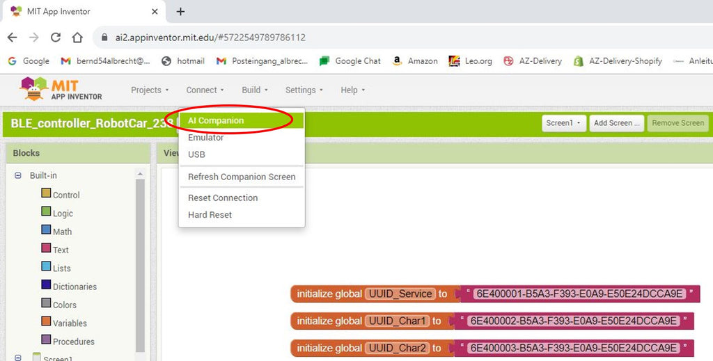
Here first of all Link to the code for the smartphone app, which you can import into MIT App Inventor in order to adapt it for your own purposes if necessary. Remember that the UUID must be “unique” (at least within a radius of several hundred meters), so if necessary. request new ones and change both in the app and in the MicroPython code.

After these changes, you can either load the app provisionally with the AI Companion or compile and upload it as an Android app under the “Build” menu item. (Apple users please research on the Internet how this works on the iPhone).

|
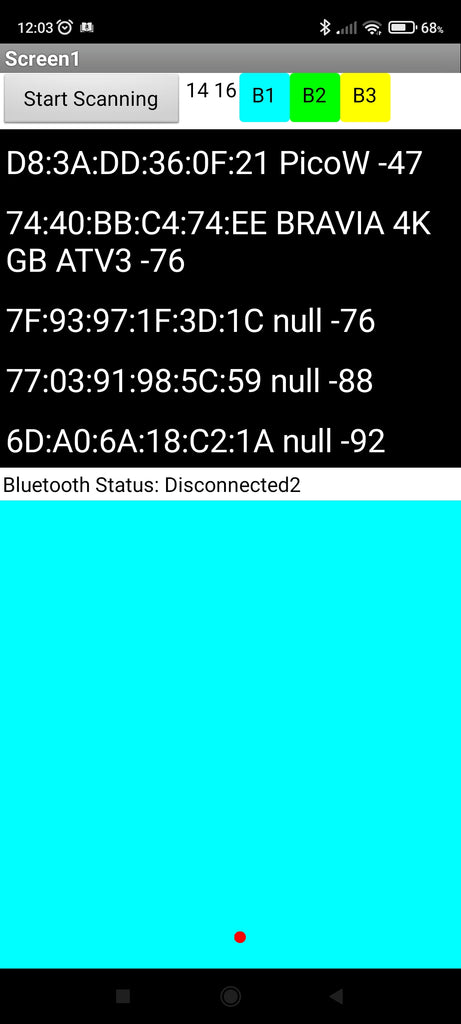
Screen shot before connecting, |
Screenshot |
 |
 |
Source code in MicroPython
Now to the MicroPython programs, which must, on the one hand, control the robot car and, on the other hand, implement the new functions. We will approach the topic of PIO using examples from the Raspberry Pi Foundation and its magazines. These program parts later complement the program used in the previous part.
You can often find the PIO assembly language program for the built-in LED (without W on the Pico!), i.e. pin 25.
# Example using PIO to blink an LED and raise an IRQ at 1Hz.
import time
from machine import Pin code
import rp2
.asm_pio(set_init=rp2.PIO.OUT_LOW)
def blink_1hz():
# Cycles: 1 + 1 + 6 + 32 * (30 + 1) = 1000
irq(rel(0))
set(pins, 1)
set(x, 31) [5]
label("delay_high")
nope() [29]
jmp(x_dec, "delay_high")
# Cycles: 1 + 1 + 6 + 32 * (30 + 1) = 1000
nope()
set(pins, 0)
set(x, 31) [5]
label("delay_low")
nope() [29]
jmp(x_dec, "delay_low")
# Create the StateMachine with the blink_1hz program, outputting on Pin(25).
sm = rp2.StateMachine(0, blink_1hz, freq=2000, set_base=Pin code(25))
# Set the IRQ handler to print the millisecond timestamp.
sm.irq(lambda p: print(time.ticks_ms()))
# Start the StateMachine.
sm.active(1)
Not surprisingly, you have to import modules or parts of them at the beginning:
import time
from machine import Pin code
import rp2
There is rp2 a microcontroller-specific module for the Pico, the others are assumed to be known. When calling the methods of this module, “rp2.” must be prefixed. Alternatively you could have used the following code:
from rp2 import PIO, StateMachine, asm_pio
Next, let's look at the lines
.asm_pio(set_init=rp2.PIO.OUT_LOW)
and
sm = rp2.StateMachine(0, blink_1hz, freq=2000, set_base=Pin code(25))
First we use the @asm_pio-decoratorto inform MicroPython that a method is written in PIO assembly language. We want the method set_init to use a GPIO as an output. A parameter is first passed to tell it the initial state of the pin (LOW).
Then we instantiate the StateMachine and pass some parameters
- the number of the StateMachine (there are eight, i.e. numbers 0 to 7)
- the program that the StateMachine should execute (here blink_1hz, without brackets)
- the frequency at which we want it to run
- the pin on which the set command should act (here the built-in LED in the Pico without Wifi/BT)
The machine language PIO assembly only knows a few commands, some of which we use in the self-defined function blink_1hz() recognize. Each instruction lasts one clock cycle, the numbers in square brackets represent further appended cycles. At the selected frequency of 2000Hz, 1000 cycles should be used for the LED to be switched on and off, which allows it to flash every second.
The interrupt request ( irq(rel(0)) ) is used in the main program to output a timestamp.
The set command is used in two ways:
    set(pins, 1)
    #or.
    set(pins, 0)

    #oder
    set(x, 31) [5]
Once the pin specified during instantiation is set to 1 (HIGH) or 0 (LOW);
in the second case, one of the scratch registers named x is set to 31 followed by [5] (wait) cycles. The addition [5] is referred to as an “instruction modifier” (see below)
With the instructions
label("delay_high") or. label("delay_low")
jump addresses are defined for the queues to which the jump command - jmp(condition, label) - refers. This is carried out until x becomes 0. Initial value was 31 (see above), with each pass the value with the first argument becomes jmp(x_dec, "delay_low") reduced by 1 (“decrement”).
At this point it makes sense to introduce all the commands of the machine language PIO assembly and the other “jump conditions” (condition) as well as the registers of the StateMachine for better understanding, because most of the conditions are attached to the scratch registers X and Y as well as the output shift Register (OSR) linked:
Here are the nine “instructions” with a short explanation:
- jmp() - Jump command, transfers control to another location in the code
- wait() - program flow pauses until a predetermined event occurs
- in_() - Bit shift from a source (Scratch Register or Pins) into the Input Shift Register (ISR)
- out() - Bit shift from the Output Shift Register (OSR) to a target
- push() - sends data to the RX FIFO
- pull() - receives data from TX FIFO
- mov() moves data from a source to a destination
- irq() sets or clears the IRQ flag (interrupt)
- set() writes a value to a target (register or pin)

StateMachine (“state machine”) with shift registers ISR and OSR, scratch registers x and y, the clock divider, the program counter (abbreviated as PC in the picture), and the control logic
(Image: Raspberry Pi Foundation)
And the jump conditions for jmp:
- (no condition) Jump command without conditions
- not_x Jump command if x == 0
- x_dec Decrement x (minus 1) and jump command if x != 0
- not_y Jump command if y == 0
- y_dec Decrement y (minus 1) and jump command if y != 0
- x_not_y Jump command if x != y
- pin code Jump command when pin is “not low”
- not_osr Jump command if Output Shift Register (OSR) is not empty
Back to our robot car. This should now have a blue flashing light when the first button (top left button) is pressed in the app on the smartphone.
The three buttons have the values 1, 2 and 4. The sum of the activated buttons results in the last digit of our five-digit code. This is broken down into its components as follows:
code = str(code)[2:-5] # necessary only for Smartphone APP
code = int(code)
cy = int(code/1000) # digit 1 and 2 # for forward/backward
cx = int((code-1000*cy)/10) # digit 3 and 4 # for left/right
cb = code - 1000*cy - 10*cx # digit 5 # for selected buttons
Which button(s) are pressed is determined by the if queries cb & Number:
if cb & 1 == 1: #1. Button
if cb & 2 == 2:     #2. Button
if cb & 4 == 4: #3. Button
The AND operation & also recognizes multiple pressed buttons. The third button (value 4) is a placeholder for switching between remote control and autonomous mode (not yet implemented).
As described above, we instantiate the StateMachine 0 with the line
sm0 = rp2.StateMachine(0, blink_1hz, freq=2000, set_base=Pin code(14))
The blue LED is connected to GPIO 14 (physical pin 19) with a series resistor of approx. 200 ohms. With
if cb & 1 == 1:
    print("blink")
    sm0.active(1)
else:
    sm0.active(0)
The StateMachine is activated at cb & 1 == 1 (also at 3, 5 and 7 because of the & link), otherwise deactivated.
In the next step I would like to add a buzzer as a siren. In the first attempt I take an active buzzer and connect it to pin 16. After many wrong turns, I am content with the fact that the buzzer also sounds every second, and so does the PIO program blink_1hz used. However, we have to “register” a second pin and use it in the @asm_pio-decorator add to:
.asm_pio(set_init=(rp2.PIO.OUT_LOW, rp2.PIO.OUT_LOW)) # for two pins (both OUT and LOW)
Then we instantiate a second StateMachine sm1 with GPIO 16 (phys. pin 21)
sm1 = rp2.StateMachine(1, blink_1hz, freq=2000, set_base=Pin code(16))
because the siren should be switched on or off when the second button is pressed.
if cb & 2 == 2:          # True also with cb==4 or cb==6
    print("active buzzer also blink_1hz")
    sm1.active(1)
else:
    sm1.active(0)
My attempt at a second PIO function based on the first function blink_1hz programming ended with error messages that I couldn't explain. So first be satisfied with what you have achieved and take a break.
I know from other microcontrollers that it is possible to generate different tones when using a passive buzzer. Maybe someone has already tried this with the Pico and PIO?
So fire up the search engine and link “PIO” and “Tones” in addition to “Raspberry Pi Pico”. I found what I was looking for with Ben Everard, editor-in-chief of “Hackspace” magazine.
He wrote a MicroPython module called PIOBeep.py and a demo program with the song Happy Birthday. It sounds horrible, but you can recognize the melody. Based on the Martin horn, I would only like to use the frequencies 440Hz (pitched tone a) and 587 Hz (the d above), but I decided to use the tone sequence “tu-ta-ta-tu” to avoid confusion with the rescue vehicles. Here is the code for the module, where we will get to know further elements of the PIO assembly language.
Source: https://github.com/benevpi/pico_pio_buzz
from machine import Pin code
from rp2 import PIO, StateMachine, asm_pio
from time import sleep
max_count = 5000
freq = 1000000
#based on the PWM example.
(sideset_init=PIO.OUT_LOW)
def square_prog():
label("restart")
pull(noblock) .side(0)
mov(x, osr)
mov(y, isr)
#start loop
#here, the pin is low, and it will count down y
#until y=x, then put the pin high and jump to the next section
label("uploop")
jmp(x_not_y, "skip_up")
nop() .side(1)
jmp("down")
label("skip_up")
jmp(y_dec, "uploop")
#mirror the above loop, but with the pin high to form the second
#half of the square wave
label("down")
mov(y, isr)
label("down_loop")
jmp(x_not_y, "skip_down")
nop() .side(0)
jmp("restart")
label("skip_down")
jmp(y_dec, "down_loop")
class PIOBeep:
def __init__(self, sm_id, pin):
self.square_sm = StateMachine(0, square_prog, freq=freq, sideset_base=Pin(pin))
#pre-load the isr with the value of max_count
self.square_sm.put(max_count)
self.square_sm.exec("pull()")
self.square_sm.exec("mov(isr, osr)")
#note - based on current values of max_count and freq
# this will be slightly out because of the initial mov instructions,
#but that should only have an effect at very high frequencies
def calc_pitch(self, hertz):
return int( -1 * (((1000000/hertz) -20000)/4))
def play_value(self, note_len, pause_len, val):
self.square_sm.active(1)
self.square_sm.put(val)
sleep(note_len)
self.square_sm.active(0)
sleep(pause_len)
def play_pitch(self, note_len, pause_len, pitch):
self.play_value(note_len, pause_len, self.calc_pitch(pitch))
Mit der Verlagerung des Programmcodes in ein Modul ist dieser leichter portierbar in andere Anwendungen. Die Grundidee ist Verwendung von Pulsweiten-Modulation (PWM) mit 50% Duty Cycle, also eine Rechteckspannung mit gleichen Ein- und Ausschaltzeiten.
Unterschiede zum vorherigen PIO-Assembly-Programm:
Mit dem Importieren der rp2-Modulteile durch
from rp2 import PIO, StateMachine, asm_pio
kann man beim Aufruf von PIO, StateMachine und asm_pio auf das vorangestellt rp2. verzichten.
Beim @asm_pio-decorator und in der folgenden PIO-Assembler-Funktion werden anstelle von set_init und set() für das Schalten der GPIO-Pins sideset_init und .side() verwendet.
Während set() einer der neun Befehle (s.o.) ist, wird die Anweisung .side() als „instruction modifier“ bezeichnet und an einen anderen Befehl angehängt.
Die “instruction modifiers” sind:
- .side() - setzt den/die side-set pins zu Beginn der Anweisung
- [number] Warteschleife Anzahl Zyklen nach Ende der Anweisung
Noch ein Wort zu nop(): Diese Anweisung gehört nicht zu den neun Befehlen und wird als „Pseudo Instruction“ bezeichnet, die als mov(y, y) assembliert wird und nichts bewirkt.
In meinem MicroPython-Programm muss ich nun zusätzlich das Modul PIOBeep (das selbstverständlich auf dem Pico, ggf. im Unterverzeichnis lib, abgespeichert werden muss) importieren und weitere Zeilen aus dem Beispiel kopieren.
import PIOBeep
beeper = PIOBeep.PIOBeep(0,16)
# frequencies of the notes, standard pitch (Kammerton a) is notes[5]=440 Hz
notes = [261, 293, 330, 349, 392, 440, 494, 523, 587, 659, 698, 784, 880, 988, 1046]
notes_val = []
for note in notes:
    notes_val.append(beeper.calc_pitch(note))
#the length the shortest note and the pause
note_len = 0.1
pause_len = 0.1
Für den Aufruf der Sirene definiere ich eine Funktion
def tutatatu():
    global buzzTime
    buzzTime = time.ticks_ms()
    beeper.play_value(note_len*4, pause_len, notes_val[8])
    beeper.play_value(note_len*2, pause_len, notes_val[5])
    beeper.play_value(note_len*2, pause_len, notes_val[5])
    beeper.play_value(note_len*4, pause_len, notes_val[8])
Das Einschalten der Sirene und der Wiederholungen nach 10 Sekunden erfolgt im Hauptteil des Programms
if cb & 2 == 2:
    print("tutatatu")
    ticksNow = time.ticks_ms()
    print("ticksNow = ", ticksNow)
    print("buzzTime = ", buzzTime)
    if time.ticks_diff(ticksNow,buzzTime) > 10000:
        tutatatu()
else:
    passport
Because the module PIO beep which uses StateMachine 0, I now have to change the StateMachine for the blue LED to
sm1 = rp2.StateMachine(1, blink_1hz, freq=2000, set_base=Pin code(14))
Here is the complete program for my robot car with blue lights and siren Download.

Have fun trying it out or adapting it to your own projects.


