
This post is also available as PDF document for download.
This article is about a special shape, the transmission of Christmas greetings. Eight LEDs are used, which are controlled by an ESP32/ESP8266 via a PCF8574 (A) port expansion module. The LEDs are placed in a line on a hole grid board together with the PCF8574.
The required bit patterns for the letters of the message make the LEDs shine. The controller ensures this. And so that he knows when he should start with the job to transmit patterns for patterns for PCF8574, we donate an accelerator module (acceleration sensor).
The movement of the circuit creates the letters of the message in the room, which should best be darkened, because the patterns occur in changing locations. I will tell you how the interaction works in today's post
Micropython on the ESP32 and ESP8266
today
Christmas greetings via shaking text
I have already described the task of the circuit and the micropython program that we will design. How can the plan be implemented and why did I choose the components? Let's examine the background.
I start with the definition of a letter. To determine the pattern, I created and printed out a grid with the help of a drawing program (for example Libre Office Draw). You can have a page with 8 times 7 blocks here download. Let's take a look at how the letter "A" is encoded.

Figure 1: letter matrix
The fields were marked on the expression with a pen, which will later light up. So you determine how the signs should look. The width, originally set on seven columns, can also be changed. A drawing set with a fixed width becomes a proportional sign set. The "I" is then, for example, narrower than a "W". The program will take this into account in a very simple way.
As in Figure 1, the column patterns follow each other, follow the light patterns of the LED line in terms of time and of course also spatially moved when moving the entire structure on the side. We'll think about this later. Figure 2 shows a fluctuating back and forth movement.

Figure 2: Free -floating greeting text
Let's start with the discussion of the hardware.
Hardware
Which controller is used is a free choice. For program development, I always like to have a module with a flash key because this gives me the opportunity to leave a program in an orderly manner. If the scope of the project allows it, I would also like to use controller boards, which on the Breadboard still release a contact series for jumper cables. That's why I have an ESP8266 when developing the circuit Amica Used, it also has a flash button on board.

Figure 3: ESP8266 and GY-271
|
2 |
D1 Mini Nodemcu with ESP8266-12F WLAN module or D1 Mini V3 Nodemcu with ESP8266-12F or Nodemcu Lua Amica Module V2 ESP8266 ESP-12F WiFi or Nodemcu Lua Lolin V3 Module ESP8266 ESP-12F WIFI or ESP32 Dev Kit C V4 unplacerated or |
|
1 |
|
|
8 |
LEDs 3mm Ø z. B. out of LED light -emitting diodes range kit, 350 pieces, 3mm & 5mm, 5 colors or Jumbo-Leds 8mm Ø *** ***** |
|
8 |
Resistance z. B. out of Resistance resistor kit 525 pieces Resistance range **** |
|
8 |
Resistance 47Ω ***** |
|
8 |
Resistance 10kΩ ***** |
|
8 |
PNP transistors BC558 or the like ***** |
|
1 |
IC version 16-pin |
|
1 |
Electrolytic capacitor 470µF / 16V z. B. out of Elko range electrolytic capacitor ***** |
|
1 |
|
|
1 |
|
|
1 |
|
|
various |
Jumper Wire cable 3 x 40 pcs. 20 cm M2M / F2M / F2F each possibly too |
|
optional |
* There is for this variant Board-layouts for download
** The mini version of the circuit can also be easily wired on a perforated grid board using the layout.
*** can only be used for the large circuit booth.
**** The resistance values are based on the LED color used (see text)
***** for the equipping of the big layout
The circuits
The circuit can be set up in different variants. It starts with the selection of the booth size. There is a layout for jumbo LEDs with a diameter of 8mm and a mini variant with 3mm LEDs. The small variant can also be equipped and wired on the linked hole grid boards, following the layout. How you can produce PCBs yourself using the ironing or light paus process here described. The PDF file with the layouts Download the link. The printed templates are placed directly on the board with the print page. The duo then comes under the iron or on the UV light box.
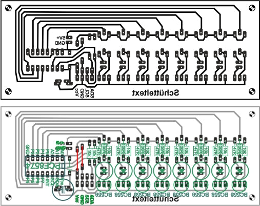
Figure 4: circuit with Jumbo-Leds

Figure 5: circuit mini version
Here is the circuit diagram for the somewhat more complex circuit with the jumbo LEDs. In order to achieve greater brightness, the LEDs are connected to a 5V source, which also supplies the controller, an ESP8266 D1 Mini. The plan also shows the connection of the GY-521 module and a PCF8574 module. When wiring the mini version, please follow the layout in Figure 5. The cathode of an LED is always the shorter connection (short as cathode). In addition, the base ring of the housing is flattened on the cathode side.

Figure 6: LED line-circuit diagram with PCF8574 module

Figure 7: LED line maxi
What does the PCF8574 module do? Well, it ensures that all LEDs of the column at the same time light up. If I were to switch the LEDs over separate GPIOs, the forced would have to happen time -moved, which would lead to a deformation of the letters. With the portrait module, which receives its bit pattern for the outputs via the I2C bus and only then implements in parallel, all relevant positions are switched simultaneously. There are instructions on an ATMEGA328 that control all accessible bits of a port together. Unfortunately, the ESPs do not have this option. Hence the detour via the PCF8574.
Instead of the PCF8574 module As shown in Figure 6, a PCF8574-IC Used, we have to take into account that the I2C bus lines with a pull-up resistor from 4.7kΩ to 10k must be drawn to VCC. These are usually already installed in I2C modules. Together with the GY521 module on the bus, it should also work without the two pullups, because it is enough if the resistances are inserted at one point. The INT management is not used in this project.

Figure 8: SDA-SCL circuit

Figure 9: LED line Mini (with yellow 3mm LEDs)
The outputs of the PCF8574 are realized by a counter-clate CMOS level. The lower transistor pulls the output to GND potential when we send a 0 to this level. 1 lays the output via the 100µA constant current source on VCC potential. But that also means that a current sink can pull a maximum of 100µA out of the line at the PX output. This is not enough to control a subsequent transistor level and certainly not enough to operate an LED.

Figure 10: Inner life of the PCF8574
For this reason, the transistors in Figure 5 of the type PNP. In order for the BC558 to be switched through, its basis must be drawn to GND potential. This can be done by the output of the PCF8574 and it can also pull the collector of the LEDs in the mini circuit to mass and accommodate up to a maximum of 25mA, which are delivered by the LED. In the present circuit, the 47Ohm resistors allow a current of approx. 11 mA. The BC558 base current, together with the 100 ohm and 10kΩ resistors, delivers approx. 2.7mA. Both are in the green area and can be recorded by the PCF8574 output and paid according to GND.

Figure 11: LED directly on the PCF8574
Now this results in the problem that in the character definitions there is a 1 for a bright LED, but the PCF8574 has to deliver a 0 at the corresponding output. The controller must therefore negate the byte value before the output on the PCF8574. This happens in the program code by exext (XODer) with 0xff - all problems solved - almost!
There is still the matter with the current limitation resistors that are switched into row with the LEDs and have to be adapted depending on the LED color. The forward or passage voltage of the LED, together with the targeted current, ultimately determines the value of the row resistance. The forward voltage depends on the color of the LED and can be found in the data sheet. The following context arises very roughly.
Color UV
Red 1.8V
Yellow 1.9V
Green 2.1V
Blue 2.8V
Violet 3.2V
white 3.2V
So much tension has to fall off the resistance that the VCC operating voltage on the LED survives exactly the forward voltage. The calculation example shows how it works.
VCC = 3.3V
LED color: yellow
UV = 1.9V
UR = 3.3V - 1.9V = 1.4V
Target current strength IZ = 8mA = 0.008a
Resistance formula: R = U / i = 1.4V / 0.008A = 175 V / A = 175 Ω
In the E12 series, the corresponding values are 180Ω or, if a bit more electricity can be, 150Ω, which results in a good 9mA.
The software
For flashing and the programming of the ESP32:
Thonny or
Used firmware for the ESP32:
Used firmware for the ESP8266:
The micropython programs for the project:
mpu6050.py: Driver for the GY-521 module
shakingext.py: Demosoftware
Micropython - Language - Modules and Programs
To install Thonny you will find one here Detailed instructions (English version). There is also a description of how that Micropython firmware (As of 18.06.2022) on the ESP chip burned becomes.
Micropython is an interpreter language. The main difference to the Arduino IDE, where you always flash entire programs, is that you only have to flash the Micropython firmware once on the ESP32 so that the controller understands micropython instructions. You can use Thonny, µpycraft or ESPTOOL.PY. For Thonny I have the process here described.
As soon as the firmware has flashed, you can easily talk to your controller in a dialogue, test individual commands and see the answer immediately without having to compile and transmit an entire program beforehand. That is exactly what bothers me on the Arduino IDE. You simply save an enormous time if you can check simple tests of the syntax and hardware to trying out and refining functions and entire program parts via the command line before knitting a program from it. For this purpose, I always like to create small test programs. As a kind of macro, they summarize recurring commands. Whole applications then develop from such program fragments.
Autostart
If the program is to start autonomously by switching on the controller, copy the program text into a newly created blank tile. Save this file under boot.py in WorkSpace and upload it to the ESP chip. The program starts automatically the next time the reset or switching on.
Test programs
Programs from the current editor window in the Thonny-IDE are started manually via the F5 button. This can be done faster than the mouse click on the start button, or via the menu run. Only the modules used in the program must be in the flash of the ESP32.
In between, Arduino id again?
Should you later use the controller together with the Arduino IDE, just flash the program in the usual way. However, the ESP32/ESP8266 then forgot that it has ever spoken Micropython. Conversely, any espressif chip that contains a compiled program from the Arduino IDE or AT-Firmware or Lua or ... can be easily provided with the micropython firmware. The process is always like here described.
The shaking program
In the event that you want to try the circuit first, the structure on a Breadboard is recommended. The one linked above offers plenty of space for all components and we can start discussing the refreshingly small program.
As already mentioned at the beginning, the program automatically works on both controller families. I have an ESP8266 - Amica-Board used because it can make do with just one Breadboard. Because I had already made the PCBs for the LEDs for test purposes, only the ESP8266 D1 Mini and the GY-271 module are on the Breadboard. I screwed the battery, breakboard and LED PCB onto a plywood plate so that I can shake all parts together and nothing goes. For the attempts to shake, you should also separate the structure from the USB so that the socket on the controller is not damaged in the case of violent movements. The program is under the name main.pyas described above, uploaded to the flash of the ESP8266. After a reset, the controller then starts autonomously without a USB connection.
The import business for our program is very clear. In the last line we import from the module MPU6050 the class Accel. The file mpu6050.py It must be in the flash of the controller. The other classes and methods are already included in the core of Micropython.
 From machine import Softi2c,Pin code
 From time import Sleep_ms
 import sys
 From MPU6050 import Accel
Then the selection of the controller type falls. The text constant sys.platform Inform us about the controller type. According to the standard specifications, we instance an I2C bus object. The transfer frequency of 100000kHz, which could work for the bus, according to the data sheet of the PCF8574, which could work with 400000kHz.
 IF sys.platform == "ESP8266":
     I2C=Softi2c(scl=Pin code(5),sda=Pin code(4), freq=100000)
 elif sys.platform == "ESP32":
     I2C=Softi2c(scl=Pin code(22),sda=Pin code(21) ), freq=100000)
 Else:
     raise Runtime("Unknown Port")
We hand over the I2C object to the constructor of the MPU6050 class and receive such an instance. Then we contribute to the liquid conversation between the controller and the periphery by declaring the device addresses of PCF8574 and MPU6050.
MPU=Accel(I2C)
Hwadrpcf=0x38
Hwadrpu=0x68
The button object for the controlled program termination and an outcome for measuring the frequency for the transmission of the characters are determined. As a button, I take the flash button of the ESP8266 module.
 button=Pin code(0,Pin code.IN,Pin code.Pull_up)
 trigger=Pin code(14,Pin code.OUT, value=0)
We put the drawing matrix in the form of one Dictionarys firmly. In the curly brackets, key and value pairs are listed, separated by commas. The key is an Ascii sign, according to a colon, the assigned value follows in the form of one Tuels. I have already described how the field values of the matrix are determined above. The last column, the last hexadecimal number, is always 0x00 so that the characters do not glue together immediately like the climbing. Feel free to add more separating columns, according to your feeling.
 sign={
     "F":(0xff,0x90,0x90,0x90,0x80,0x80,0x00),
     "R":(0xff,0x90,0x90,0x90,0x9c,0x63,0x00),
     "O":(0x7e,0x81,0x81,0x81,0x81,0x7e,0x00),
     "H":(0xff,0x10,0x10,0x10,0x10,0xff,0x00),
     "A":(0x3f,0x70,0x90,0x90,0x70,0x3f,0x00),
     "E":(0xff,0x91,0x91,0x91,0x81,0x81,0x00),
     "S":(0x61,0x91,0x91,0x91,0x91,0x8e,0x00),
     "T":(0x80,0x80,0xff,0x80,0x80,0x80,0x00),
     "W":(0xfe,0x01,0x1e,0x01,0x06,0xf8,0x00),
     "I":(0x81,0xff,0x81,0x00),
     "N":(0xff,0x40,0x30,0x0c,0x02,0xff,0x00),
     "C":(0x7e,0x81,0x81,0x81,0x81,0x42,0x00),
     "*":(0x4a,0x2c,0xf8,0x1e,0x34,0x52,0x00),
     "P":(0xff,0x90,0x90,0x90,0x90,0x60,0x00),
     "U":(0xfe,0x01,0x01,0x01,0x01,0xfe,0x00),
     "J":(0x84,0x82,0x81,0x81,0x82,0xFC,0x00),
     " ":(0x00,0x00,0x00,0x00,0x00,0x00,0x00),
     }
This is followed by definitions for functions for cartoons, writereg() Send a byte to a periphery device on the I2C bus. The hardware or device address, the register address and the data byte are to be handed over.
 def writereg(hwad, ADR, dat):
     I2C.writeto(hwad,bytearar([ADR,dat]))
It is important to convert the register address and bytest value into a bytearar. This is necessary because the method writeto() of the i2C instance not all of them, but only objects that the so-called Buffer protocol support, these are objects of the type bytes- or bytearar. We build the two integers into one list One that we then convert to a bytearar by the list of the constructor of the class bytearar hand over.
Please note that the following command brings a completely different result.
 >>> bytearar(2,3)
 bytearar(B '\ x00 \ x00')
Here a bytearar with two fields is generated with the default value 0x00 and the 3 is simply eaten by the constructor without comment, you can get it!
The PCF8574 is a very frugal guy that does not even have register. Writing instructions go directly into the starting buffer. That means it must, or better, no register address be sent. PCFWrite() that takes into account.
 def PCFWrite(hwad, dat):
     I2C.writeto(hwad,bytearar([dat]))
The hardware address of the chip is still handed over, because up to eight PCF8574 can be on the bus. This is made possible by the three address pins A0, A1 and A2. For our project, all three pins are on GND potential. This addresses the PCF8574 with its basic address. But even that can vary, because there are different versions of this building block. It will be best if you put the PCF8574 on the bus alone and with I2C.Scan() determine his address. That goes in Replica so:
 >>>From machine import Softi2c,Pin code
 >>> I2C=Softi2c(scl=Pin code(5),sda=Pin code(4), freq=100000)
 >>> hex(I2C.scan()[0])
 '0x38'
My PCF8574AP So has the hardware address 0x38, the 0x40 and the 0x70 for the PCF8574 can be found for the PCF8574 and for the PCF8574A. The mystery becomes complete because we I2C.Scan() the 7-bit address delivers and im data sheet but the 8-based address is specified with the R/W-bit. Also for I2C.Writeto() and I2C.Readfrom() If the 7-bit address is required because Micropython automatically adds the R/W-Bit, depending on the operation. The values from the data sheets must therefore be pushed to the right by a bit.
 >>> hex(0x40 >> 1)
 '0x20'
 >>> hex(0x70 >> 1)
 '0x38'
The scan has therefore correctly located the PCF8574AP as an A-type.
In order to read a byte from the bus, for a building block that uses register, hardware address and register address must be handed over. Both are sent to the external chip.
readfom() then reads one bytes-Plower 1. By indexing with [0] we get the decimal value of this first bytes.
 def readreg(hwad, ADR):
     I2C.writeto(hwad,bytearar([ADR]))
     return self.I2C.readfom(hwad,1)[0]
A function follows, which the bit matrix can send for a sign to the PCF8574.
 def showchar(char,delay=5):
     C=(0x10,0x10,0x10,0x10,0x10,0x10,0x00)
     IF char in sign:
         C=sign[char]
     for Val in C:
         trigger.value(1)
         Val ^= 0xff
         PCFWrite(Hwadrpcf,Val)
         Sleep_ms(delay)
         trigger.value(0)
showchar() takes the ASCII sign and optionally in the keyword parameter delay The time of the advertisement in milliseconds. If a non -defined sign has been handed over, we put in C The pattern for a hyphen, "-". Will the sign as a key in the dictionary sign found, we prove C With its pattern.
In C Is now a drawing matrix. In the for loop we feel the columns. Our trigger output goes to 1, we exade the picked value in Val With 0xff and send the result to the PCF8574. After delay The trigger pin goes to 0. The loop sends as many values as in the tupel in C are given. This allows you to display any wide patterns. We can score the trigger output with a DSO (digital memory oscilloscope) or the Logic Analyzer to determine the actual character-sequence frequency.
The next step brings the presentation of short texts. The implementation takes place analogously to showchar() by a loop. The handed over S is through the for loop spared And the found characters hike to the PCF8574.
 def show string(S, delay=5):
     for char in S:
         showchar(char, delay)
One of my shortest Main Loops Ever forms the end of the program.
 while 1:
     while Section(MPU.getvalue("Z")) < 2000:
         passport

     show string("HAPPY HOLIDAY",3)

     IF button.value() == 0:
         showchar(" ",10)
         trigger.value(0)
         sys.exit()
The inner While loop is waiting for the MPU6050 to report an acceleration signal that exceeds the limit of 2000, both in positive and in a negative direction of axis. Which axis this is with you depends on how you installed the GY-271 module. Simply orient yourself about the print on the Break Out Board. For lateral movements this is the Z axis for me, because the module is perpendicular to the Breadboard.

Figure 12: Z axis shows in the direction of movement
Then follows the string and then the key query. If it is pressed at this moment, we make the LEDs out, put the trigger output to 0 and leave the program.

Figure 13: entire structure
A consideration at the end
If a column is to be displayed base the previous one, a minimum speed must be observed. For the 8mm LEDs this is in my approach with 3ms luminance: 8mm/3ms = 2.67m/s, for the 3mm LED only 1m/s. For displaying the string "Happy Festival" with 11 • 77 columns, floating texts with 77 • 8mm = 616mm or 231mm result. Figure 2 gives an impression of what it looks like.
A task for "youth research"
Figure 2 shows the text in the reverse letter sequence. Do you find a way to change that? In principle, it is quite simple. What does the MPU6050 provide for values if the direction of the acceleration is reversed? How do you have to react to this in the program? In the end, the change is quite extensive because not only the change of direction of the movement, but also the parse of the text and the representation of the column patterns must be adjusted. Good luck with programming "SchüttelText 2.0"!
And of course I wish you a nice Advent season!


