
In the First part of this blog series we got to know the GPIOs as an outcome for LEDs, buzzer and relays. Now the programming of the GPIOs should follow as an entrance, first using the example of the button.
Required parts (as in part 1)
|
1 |
|
|
1 |
|
|
old |
|
|
1 |
|
|
Jumper cable, Button/button |
|
|
optional |
A button (button) is a spring -loaded switch that opens the circuit again after letting go. It is important to note two special features: First, a short circuit in the circuit must be avoided and secondly, the inexpensive button "bounce" (English bounce, bouncing), i.e. instead of the immediate electrical contact and open the contact.
If the GPIO PIN has been declared as an entrance, you can query the program whether a high signal (voltage approx. 2-3.3V) or a low-signal (GND = 0V to max. Approx. 1.2V) is located . So if you apply 3.3V by pressing the button, it is clearly high. If you let go of the button again, you have an undefined state. Low is only recognized if the connection to GND is established. If the button is then pressed, however, you have a rich short circuit and damaged the micro controller. A pull-down resistor of 10 kΩ can remedy this that pulls the pin on low. When the button is pressed, the condition on the pin high, there is a low current due to the resistance to GND, which is in the permissible area. The following applies: i = u / r, i.e. 3.3V / 10 kΩ = 0.33 mA.

The same applies to inverse logic: the PIN is permanently held on high via a pull-up resistor and pulled to low when the button is pressed. The nice thing is that the microcontrollers have an internal pull-up resistor that can be switched on in the program. Therefore, this circuit is used more frequently these days.

Now for programming with the Micropython module picozero. Here is the class Buttonthat at the beginning of the program
From picozero import Button
is imported, then the object button is instantiated with e.g.
button = Button(16) # GP16 = Phys. PIN 21
In the class definition you can see that there are two optional parameters that are preset:
class picozero.Button(pin code, Pull_up=True, bounce_time=0.02)
With these default settings, the two above -mentioned problems are solved. The button can be switched against GND and bumps are suppressed by a "bounce_time" of 20 ms. Of course, these values can be changed when instantiation of the object, e.g.
button = Button(17, Pull_up=False, bounce_time=0.01) # GP17 = Phys. PIN 22
Two simple sample programs, the first self -explanatory: From picozero import Button
import utime AS time
button = Button(16)
while True:
IF button.Is_pressed:
print("Button is pressed")
begin = time.Ticks_MS()
Else:
print("Button is not pressed")
sleep(0.1)

At first glance, the second example program looks like the function is pico_led.on () called. However, at Button.When_Pressed = pico_led.on no brackets () can be used. The documentation writes: The function is not called up, but a reference to the function is set up.
 From picozero import Button, pico_led   # Internal LED
 button = Button(16)         # default: pull_up = true, bounce_time = 0.02
 button.When_Pressed = pico_led.on       # Remark: No Brackets ()
 button.When_Released = pico_led.off
The program with the Micopython module is a little more complex machineHowever, which may also be used for other microcontrollers such as ESP32.
 From machine import Pin code
 import utime AS time
 button = Pin code(16, Pin code.IN, Pin code.Pull_up)
 reset = Pin code(17, Pin code.IN, Pin code.Pull_up)
 # Code line for Raspberry Pi Pico (without WLAN)
 LED_ONboard = Pin code(25, machine.Pin code.OUT)
 # Code line for Raspberry Pi Pico W (with WLAN)
 #Led_onboard = PIN ("LED", Machine.pin.out)
 while True:
     IF button.value() == 0:
         print("Button is pressed")
         LED_ONboard.on()
     IF reset.value() == 0:
         print("Reset is pressed")
         LED_ONboard.off()
     time.sleep(0.1)
In anticipation of the next section sensors, which usually only create a short switching pulse, I already have a second button to switch off by name reset introduced.
Sensors
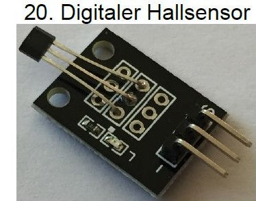
Now to the sensors that work like switches or buttons; First the purely digital sensors: (fork) light barrier, family of shaking sensors (also shock, knock), motion detectors, magnetic switch, digital hall sensor, flame sensor. (The numbers refer to the sections in the eBook for the Sensor Kit on the Atmega microcontroller.)
 |
 |
 |
 |
 |
 |
 |
 |
From picozero import pico_led, Button
import utime AS time
button = Button(16)
reset = Button(17)
while True:
button.When_Pressed = pico_led.on
reset.When_Pressed = pico_led.off
The built -in LED pico_led does not need to be instantiated. If you want to connect an external LED or a buzzer, you have to import these classes and instantiate the objects with the desired PIN number (See part 1).
Analog inputs of the Pico/Pico W
Before I often address the sensors with four connections, in addition to + and GND D0 and A0 (for digital and analogue output), I would first like to describe the analog inputs of the PICO.
Analogy input means that not only low or high is recognized, but a voltage between zero and the reference voltage (in the case of PICO 3.3V, provided that no other voltage is created on PIN 35 (= ADC_VREF)) is converted into a numerical value. The resolution is in the PICO at 12-bit, i.e. a value between 0 and 4095, but this is used with the method adc.read_u16 () From the module machine scaled on the range 0 to 65535, in the module picozero standardized to area 0 to 1 for comparison at Uno Is the resolution 10-bit, which results in a value between 0 and 1023.
The RP2040 basically has five ADC channels, of which three can be used in the Raspberry Pi Pico. ADC0 lies on GP26 (Phys. PIN 31), ADC1 to GP27 (Phys. PIN 32) and ADC2 on GP28 (Phys. PIN 34); ADC3 is connected to VSYS in the PICO and ADC4 with the internal temperature sensor, which is not very suitable for measuring the ambient temperature.
Here sample code for the module machine and then module picozero.
N.B. Basically, the module knows machine also the method adc.read_uv (), so recognizing the tension. However, this does not work with the Pico.
From machine import ADC, Pin code
import utime AS time
ADC = ADC(Pin code(26)) # Create ADC Object on ADC PIN
while True:
value = ADC.read_u16() # Read Value, 0-65535 Across Voltage Range 0.0V - 3.3V
print("Value =",value)
time.sleep(0.1)
# Potiometer Connected to GP26 (ADC0), GND and 3V3
From time import sleep
From picozero import pot
pot = pot(26)
while True:
print(pot.value, pot.voltage)
sleep(0.1)
The joystick module consists of two potentiometers and a button. Here is a program example:
 # Joystick Module Connected to GP26 (ADC0), GP27 (ADC1), GP16 (button), GND and 3V3
 From time import sleep
 From picozero import pot, Button
 potx = pot(26)
 poty = pot(27)
 button = Button(16)
 while True:
     X = potx.value
     y = poty.value
     B = button.value
     print("X =", X, "Y =", y, "B =", B)
     sleep(0.1)
Please note: Again, after calling up .value No brackets set. Otherwise you will receive the error message "... is not callable“.
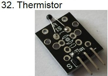
Two other sensors provide analog values and can be connected like a potentiometer: the light sensor (LDR resistance) and the thermistor.
 |
 |
Likewise, you can only switch on the light with logical links when a movement is recognized if a certain light intensity is below.
Sensors with digital and analog connections
Now to the sensors with four connections, in addition to the power supply to a digital and an analog output. Most of these sensors on the board have a small, blue trim potentiometer and an LED.
 |
 |
 |
 |
 |
 |
 |
We have already seen how the digital and how the analog signals are evaluated. So does it make sense to evaluate both signals at the same time? Yes, do it. Especially with regard to the built -in potentiometer! Because with the help of the analog values you can set the limit value on the potentiometer, in which the LED lights up and the digital pin is switched to high. Because the evaluation of the digital signal is easier and easier to implement in circuits.
One more word about the microphone modules. No language or music are recorded, it is only about the noise level! For example, a "gossip switch" is possible to use how he was realized in 1959 in the film "Bed whisper" with Doris Day and Rock Hudson without a microcontroller.
With the last two sensors you have to do without the analog signal for adjustment, but here too the sensitivity with trim potentiometers can be changed. Above all, try it out.
 |
 |


